3-9 Amplitude Accuracy Spectrum Analyzer Performance Verification
3-22 PN: 10580-00303 Rev. D Model MS20xxB MM
9. Record the Sensor B reading into the Required Sensor B Reading column of Table A-17 for MS2034B or
Table A-42 for MS2035B in Appendix A.
10. Repeat Step 8 and Step 9 for the other input levels from –4 dBm to –50 dBm.
50 MHz Amplitude Accuracy Measurements
11. Disconnect Sensor A from the 10 dB Fixed Attenuator and then install the 34NN50A Adapter to the end
of the attenuator.
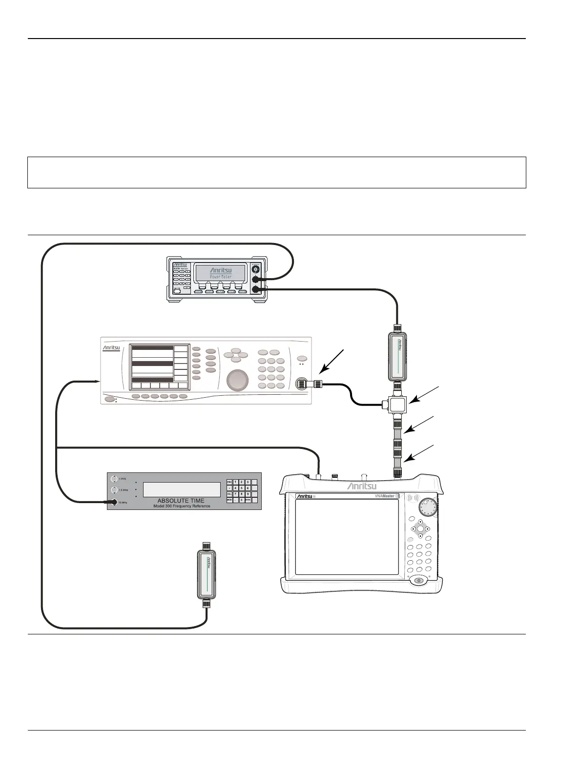
12. Connect the open end of the 34NN50A Adapter to the RF In connector of the VNA Master as shown in
Figure 3-5.
13. On the VNA Master, press the Shift key and then the Mode (9) key. Use the rotary knob to highlight
Spectrum Analyzer and then press the Enter key to switch to Spectrum Analyzer mode.
14. Press the Shift key and then the Preset (1) key. Press the Preset button on the touch screen submenu to
set the instrument to the factory preset state.
Note
To maintain test setup integrity, do not disconnect Sensor B, the Power Splitter or the Fixed
Attenuator.
Figure 3-5. 50 MHz Amplitude Accuracy Verification Test Setup
Attenuator
Adapter
10 MHz Reference
Signal Source
Power Meter
Sensor B
Power Splitter
MS203xB
Adapter
Power Charge
+/-
.
0
3
Sweep
2
Calibrate
1
Preset
6
Limit
5
Trace
4
Measure
9
Mode
8
System
7
File
Shift
Back
Enter
ESC
Sensor A

 Loading...


