Spectrum Analyzer Performance Verification 3-10 Third Order Intercept (TOI)
Model MS20xxB MM PN: 10580-00303 Rev. D 3-33
14. Disconnect the power sensor from the output of the power splitter and connect the power splitter output
to the MS203XB RF In connector through the Anritsu Model 34NN50A adapter as shown in Figure 3-9.
15. Turn On the RF of both MG3692x #1 and MG3692x #2.
16. On the MS203XB, press the Shift key and then the Trace (5) key. Press Trace A Operations, and set
# of Averages to 2.
17. After two sweeps have occurred (Trace Count 2/2 appears on the left of the display), turn on a marker,
and press Peak Search. Record the amplitude of the signal at 800.151 MHz in Table A-21 for MS2034B
or Table A-38 for MS2035B in Appendix A.
18. Change the Center Frequency of the MS203XB to 799.851 MHz.
19. After two sweeps have occurred (Trace Count 2/2 appears on the left of the display), turn on a marker,
and press Peak Search. Record the amplitude of this signal in the following tables in Appendix A.
• MS2034B – Table A-29, “Spectrum Analyzer Third Order Intercept” on page A-14
• MS2035B – Table A-56, “Spectrum Analyzer Third Order Intercept” on page A-28
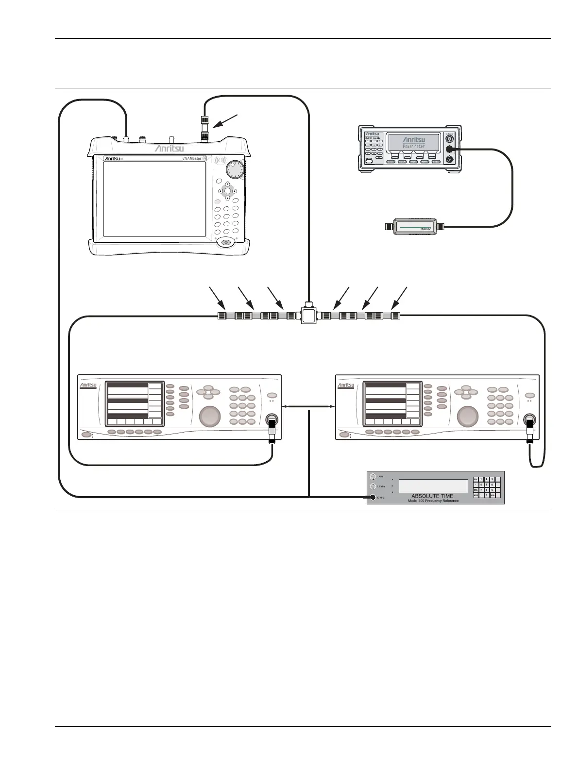
Figure 3-9. Third Order Intercept (TOI) Measurement Setup
VNA Master
Adapter
34NN50A
Power Charge
+/-
.
0
3
Sweep
2
Calibrate
1
Preset
6
Limit
5
Trace
4
Measure
9
Mode
8
System
7
File
Shift
Back
Enter
ESC
Signal Generator
Signal Generator
Sensor
10 MHz Reference
Power Meter
To
Rear
Power
Splitter
AttenuatorsAttenuators
6 dB
20 dB 20 dB 6 dB 2 dB2 dB
 Loading...


