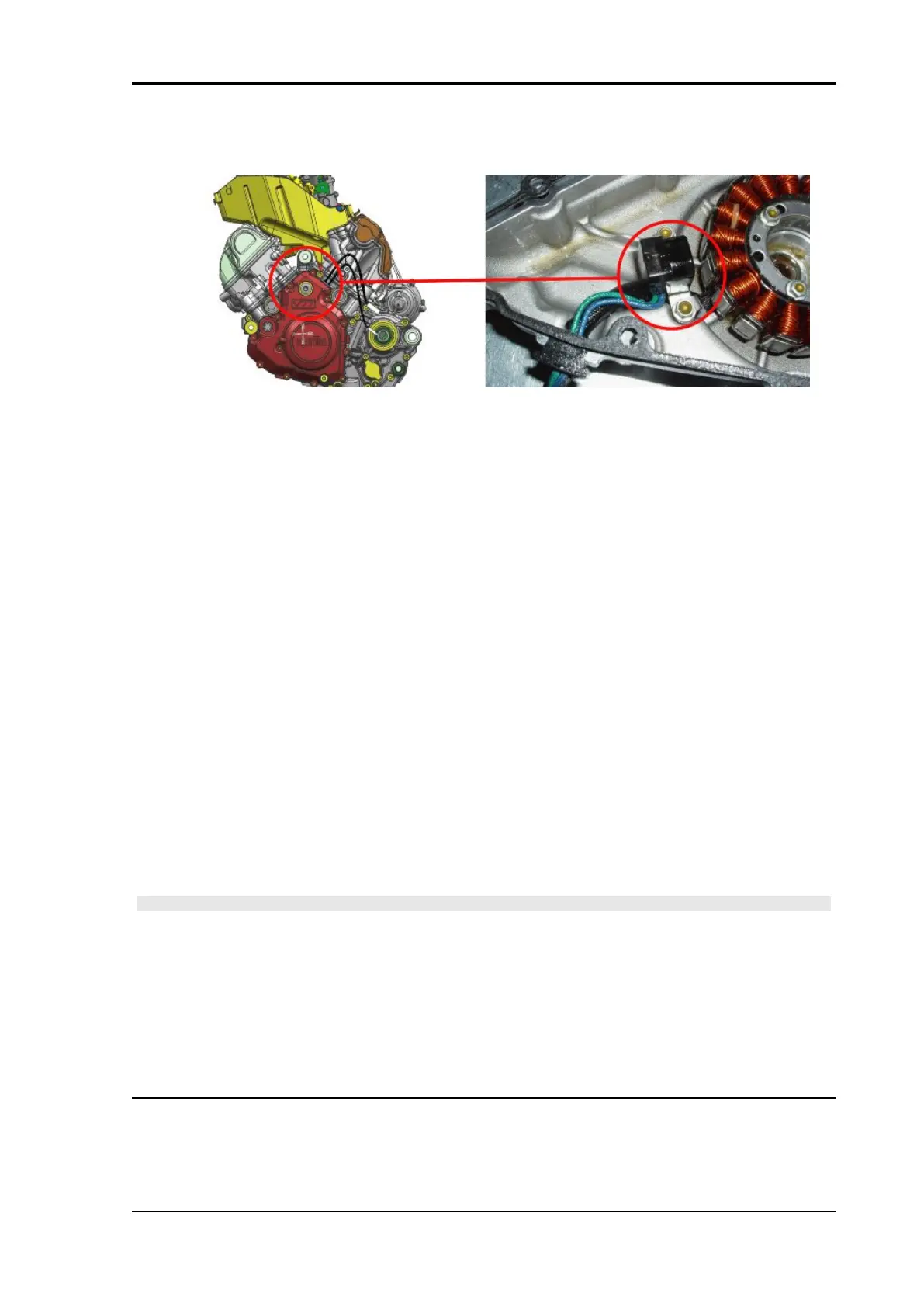
Engine rpm sensor
Engine revolution sensor - Pick up
Function
It informs crankshaft position and speed to the Walbro control unit.
Operation and operating principle
Inductive sensor: sinusoidal-type generated voltage; two teeth are missing on the flywheel for the ref-
erence position
Level in wiring diagram: revolution sensor
Position
•
sensor: inside the flywheel cover
•
connector: under the filter casing, behind the front cylinder (inside the protection rubber
housing)
Electrical characteristics:
Resistance at ambient temperature: 112 +/- 10 % Ohm
Pin-out:
•
+ (blue cable on sensor side): supply voltage 5V approx.
•
- (green cable on sensor side): ground connection
REMARK: blue/green cable on sensor side, shielding.
CAUTION
IF THE ELECTRIC CIRCUIT IS INTERRUPTED OR SHORT-CIRCUITED OR NO ERROR IS DIS-
PLAYED, CHECK THE REVOLUTION SENSOR CONNECTOR AND THE WALBRO CONTROL
UNIT CONNECTOR: IF NOT OK, RESTORE; IF OK, CHECK THAT THE SENSOR ELECTRICAL
SPECIFICATION IS THE CORRECT ONE: IF IT IS NOT, REPLACE THE SENSOR. IF IT IS THE
CORRECT ONE, CHECK THAT THERE IS CONTINUITY ON BOTH CABLES, SUPPLY INSULA-
TION AND GROUND CONNECTION INSULATION. CARRY OUT THE TESTS FROM THE SENSOR
CONNECTOR TOWARDS THE SENSOR. IF NOT OK, RESTORE THE CABLE HARNESS/RE-
PLACE THE SENSOR. IF OK, PERFORM THE TEST FROM PINS B4 AND C4 OF THE WALBRO
CONTROL UNIT CONNECTOR.
MXV 450 Electrical system
ELE SYS - 57