nector and coil connector; if NOT OK,
restore cable harness; if OK, check
that there is continuity of the supply ca-
ble between voltage regulator/battery
connector and coil connector. If OK,
check ground insulation of the positive
cable or ground insulation (with battery
connected but engine off) or that the
negative cable is shorted to positive. If
NOT OK, restore cable harness; if OK,
replace the control unit.
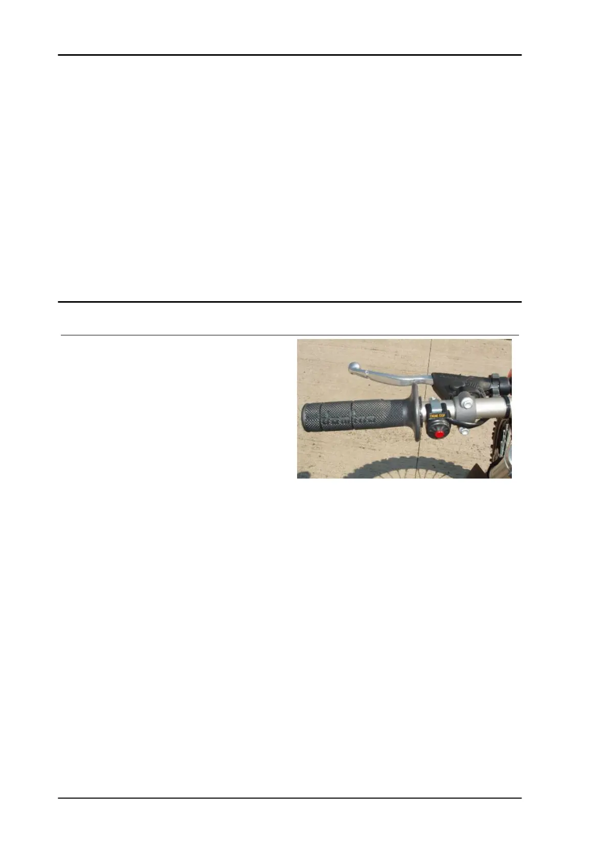
RUN/STOP switch
Function
It indicates to the control unit if the rider wishes to
stop the engine
Operation / operating principle
if the engine is to be turned off the switch must be
closed, that is the Walbro control unit must feel the
ground connection at PIN F2
Level in wiring diagram: engine stop
Position
•
on vehicle: close to the left hand grip
•
connector (if available): behind the
front number holder table
Electrical characteristics:
•
STOP position: closed circuit (continu-
ity)
•
RUN position: the circuit is open
Pin-out:
•
white/black cable (sensor side): 0V
voltage if switch is in STOP; 5V if
switch is in RUN.
•
Black cable (sensor side): always 0 V
voltage
DIAGNOSIS
Electrical system MXV 450
ELE SYS - 68