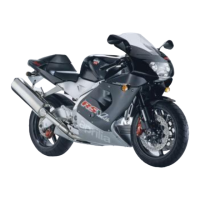
•
Lift the coil by sliding off the spark plug
tube wiring.
NOTE
UPON REFITTING, LOCK THE SPARK PLUG TUBE WITH A
PAIR OF PLIERS AND INSERT THE COIL.
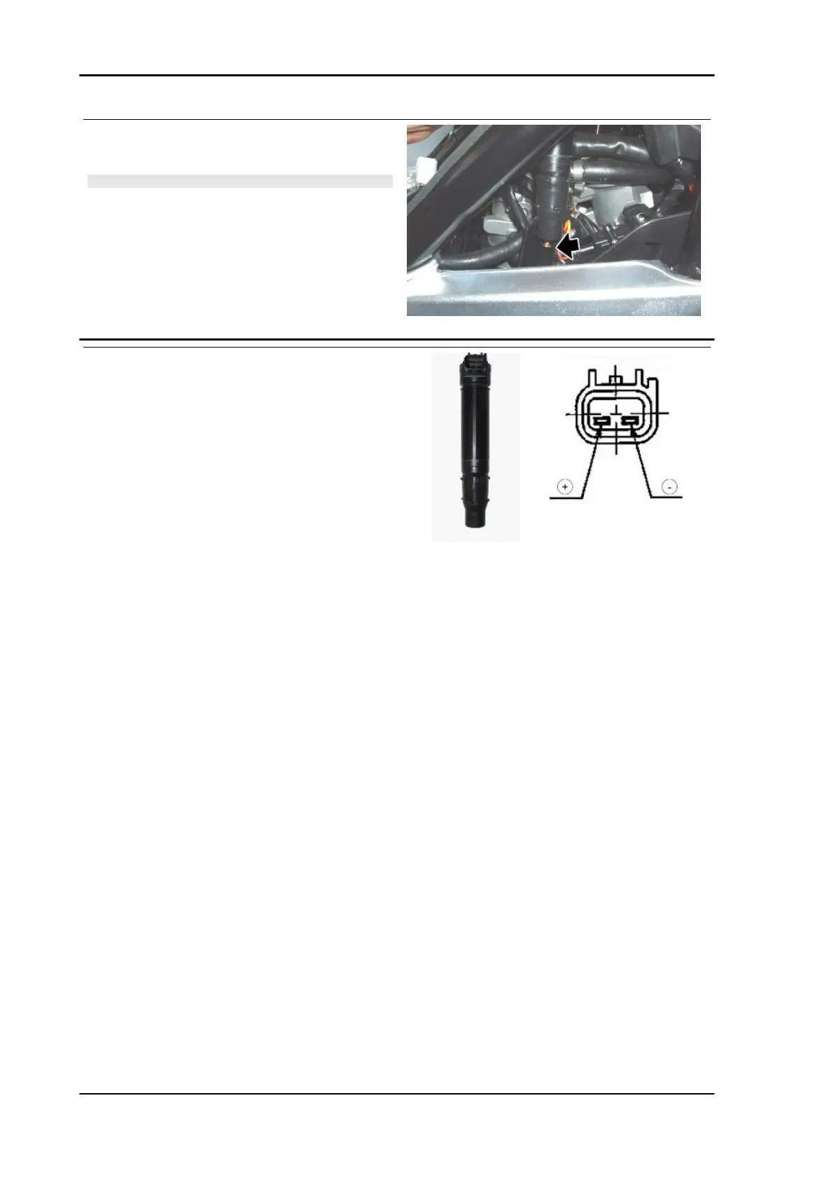
COILS
Function: spark generation
Operation / Operating principle: Inductive dis-
charge system
Level in wiring diagram: coils and injectors
Position
•
Front cylinder coil: inside the filter cas-
ing, right side
•
Rear cylinder coil: inside the filter cas-
ing, left side
•
Connector: on the coils
Electrical specifications
•
Primary winding resistance: 1.4 Ohm
+/- 15% at 20 +/- 5 °C(68 +/- 41°F)(+
and -)
•
Secondary winding resistance 3 kOhm
+/- 15% at 20 +/- 5 °C(68 +/- 41°F)(+
and output)
•
Tube resistance: 5 kOhm +/- 10%
NOTE Pay particular attention to check there
are no loose contacts on the main fastom cir-
cuit
Pin-out:
•
+ (orange/red cable): supply voltage
12V approx.
•
Front coil - (white/black cable):
ground / coil control
Electrical system MXV 450
ELE SYS - 66