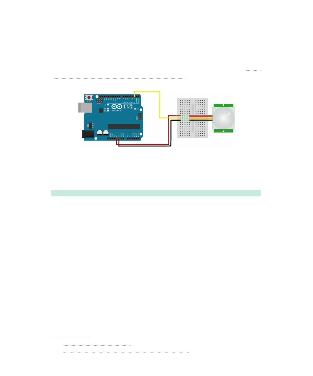
The PIR sensor has three pins: power, ground, and signal. Connect power to
the Arduino’s 5V supply, ground to one of the Arduino’s GND pins, and signal
to digital pin 2. In the following figure, you see a circuit diagram that connects
a PIR sensor from Adafruit
7
to an Arduino. Note that PIR sensors from different
vendors often differ in the order of their connectors. The PIR sensor in Figure
29, Top and bottom of a passive infrared sensor, is different, so you should
always make sure you connect the correct pins.
The PIR sensor usually also has a jumper that you can use for changing its
behavior. For our project, it has to be in position H; the jumper has to cover
the pin next to the H. (Lady Ada has an excellent tutorial on PIR sensors.)
8
Then enter the following code in the Arduino IDE:
Ethernet/MotionDetector/MotionDetector.ino
const unsigned int PIR_INPUT_PIN = 2;
Line 1
const unsigned int BAUD_RATE = 9600;
-
-
class PassiveInfraredSensor {
-
int _input_pin;
5
-
public:
-
PassiveInfraredSensor(const int input_pin) {
-
_input_pin = input_pin;
-
pinMode(_input_pin, INPUT);
10
}
-
const bool motion_detected() const {
-
return digitalRead(_input_pin) == HIGH;
-
}
-
};
15
-
PassiveInfraredSensor pir(PIR_INPUT_PIN);
-
-
void setup() {
-
Serial.begin(BAUD_RATE);
20
}
-
7.
http://www.adafruit.com/products/189
8.
https://learn.adafruit.com/pir-passive-infrared-proximity-motion-sensor
report erratum • discuss
Detecting Motion Using a Passive Infrared Sensor • 195
www.it-ebooks.info

 Loading...