VAR8 and Variants Operation, Commissioning, Fault Finding, and Maintenance Guide -
Is
Page 131 of 166
sue: 02 complete, approved
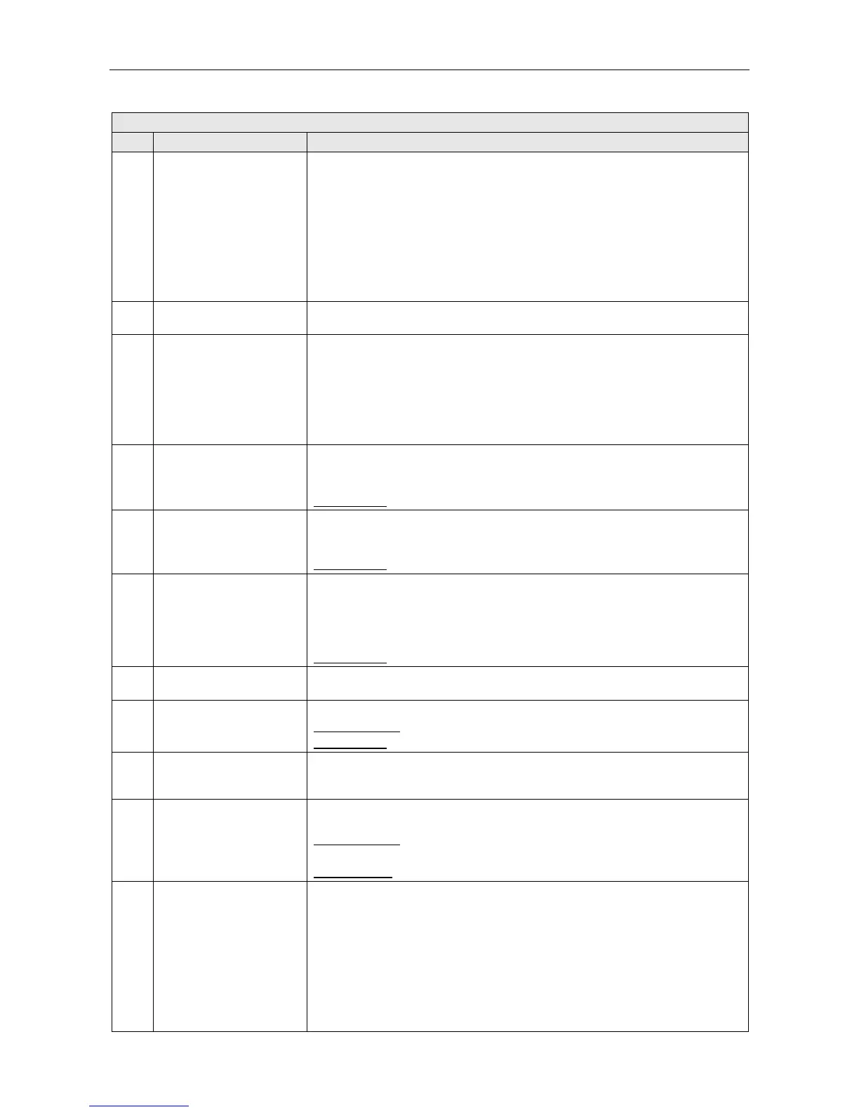
VAR8 Menu Description
Ref. Item Description/Possible Settings
21 Routing This indicates what input is currently routed to each output.
For example:
OP1 OP2 OP3 OP4 OP5 OP6 OP7 OP8
L00 L04 N02 L00 L08 N07 L00 L00
Where:
L00 = Nothing currently routed to O/P 1
L04 = Local I/P 4 currently routed to O/P 2
N02 = Network I/P 2 currently routed to O/P 3
etc.
22 Contacts
Enables the user to view the actual physical contact state (1=active, close,
0=inactive, open) on the Router and on a Remote I/O Unit.
23 ANS
Enables the user to enable the user to view the values read in dB by ANS
sensors in an output zone:
Cur = The current reading from the ANS sensor / the current attenuation level.
Act = The minimum / maximum readings from the ANS sensor, with an input
routed to the output. It measures the volume of an announcement.
Idle = The minimum / maximum readings from the ANS sensor, with nothing
routed to the output. It measures the genuine ambient noise.
24 Frame#nn -
Enables the user to scroll through the list of configured amplifier frames. When a
frame has been selected, the sub-menus are displayed.
Where: nn=1 to 63
Default value:
Lowest numbered frame
25 System
Enables user to scroll through the system fault log (history of last 200 faults).
Scrolling through the fault log is performed using up/down keys or rotary
encoder.
Default value:
The most recent record.
26 Frame#nn
Enables the user to scroll through the list of configured amplifier frames. When a
frame has been selected, the user can scroll through the fault log (history of last
200 faults) maintained for the selected frame. Scrolling through the fault log is
performed using up/down keys or rotary encoder.
Where: nn=1 to 63
Default value:
Lowest numbered frame
27 Commis
Displays the detected configuration of the frame (type and rating of amplifiers in
each of the four amplifier slots).
28 Desc Enables the user to view/edit the frame description. For reference only.
Possible values:
alphanumeric string of up to 12 characters
Default value:
blank
29 O/P Map
Enables each slot to be associated with an output. This is so that faults can be
mapped from amplifiers to zones - specifically in relation to faults displayed by
fire panel interface units.
30 Temp
Enables the user to define a temperature alarm. A fault will or not be raised if the
configured temperature at the frame is exceeded.
Possible values:
‘Not-Conf’ or ‘Config’d’
Max Temp(°C)= 15 to 99°C
Default values:
‘Not-Conf’ and ‘Max Temp(°C)=70’
31 Slot#n Enables the user to scroll through the slots in the selected frame.
Where: nn=1 to 4