VAR8 and Variants Operation, Commissioning, Fault Finding, and Maintenance Guide -
Is
Page 145 of 166
sue: 02 complete, approved
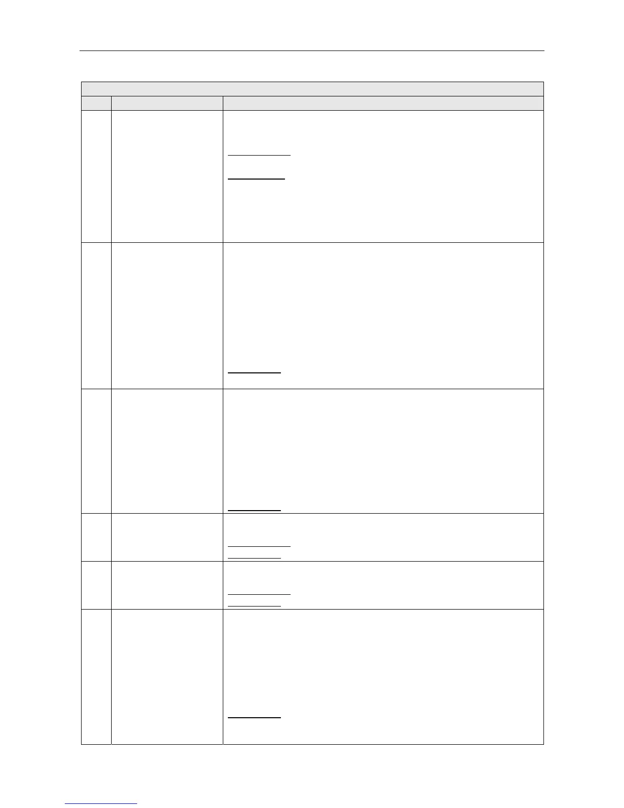
VAR8 Menu Description
Ref. Item Description/Possible Settings
150 Pri
Enables the user to allocate priority to the input source independently to each of
the Router outputs.
Equal priorities operate on a first come-first served basis.
Possible values:
Priority=01 to 19 (01 is the highest priority)
Priority=00 is available only for Mute Input.
Default values:
Fire Mic on input 1: ‘Priority-01’
Fire Mic on input 2: ‘Priority-02’
Other Mic/Line inputs: ‘Priority-11’
Music input: ‘Priority-19’
Mute input: ‘Priority-00’
L Pri is not available for Network Channel input.
151 Class
Enables the user to define the classification of announcements made from the
input channel. This classification affects the red and green LEDs of each zone
select button of the Audio Control Unit built-in microphone (if used) and Fire
Microphones connected to the ACU. From ACU V1.5.0114 or later, it is possible
to configure a microphone connected to an ACU between this mode and the
standard mode in which the ‘Busy’ LED turns ‘on’ continuously to indicate that
the zone (either one or the group of zones controlled by this button) is already in
use by another input, and the green LED indicates the zone selection state.
• ‘Non Emergency’: red LED ‘off’ + green LED ‘on’
• ‘Low Priority Emergency’: red LED flashing + green LED ‘on’
• ‘High Priority Emergency’: red LED steady ‘on’ + green LED ‘on’
Default value:
‘Non Emergency’
L Class is not available for Network Channel input.
152 Latching
Defines whether the selected Remote I/O Unit Digital Input is used to both make
and clear the route.
• ‘Not Latched’: activation of the contact initiates the route, and release of the
contact terminates it.
• ‘Latched’: a reset contact is also defined; in this configuration activation of the
first contact initiates the route, and activation of the reset contact terminates it
(provided that the first contact has been released).
If ‘Latched’ has been chosen, the user can identify the contact that will act as
the reset contact.
The reset contact may be a digital input (1 to 12).
Default value:
‘Not Latched’
153 Busy=On
Defines whether or not this route should cause busy indication on the LEDs
associated with microphone zone select buttons.
Possible values:
‘On’ or ‘Off’
Default value:
‘On’
154 DVA-Full
Defines whether, when the route is terminated, the DVA shall cease playing
immediately or play until its end.
Possible values:
‘DVA-Full’ or ‘DVA-Part’
Default value:
‘DVA-Full’
155 Zoning
Applicable when a button is configured for DVA Routing. Allows each output to
have an input associated with it. The outputs in question are the outputs of the
Slave Unit. The inputs may be one of the Audio Control Unit or Slave Unit audio
sources.
<OUTPUT nn>: List of 8 output names.
LOCAL IP: List of Slave Unit audio source names: 8xMic/Line
inputs+1xMusic input+Mute input+4xDVA inputs.
NETWORK IP: List of Audio Control Unit audio source names according to
Audio Control Unit type.
Default value:
‘Not-Conf’