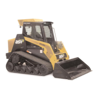
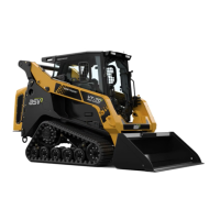
Rubber Track Loader
17. Hydraulic Pressure Check & Adjustment
2
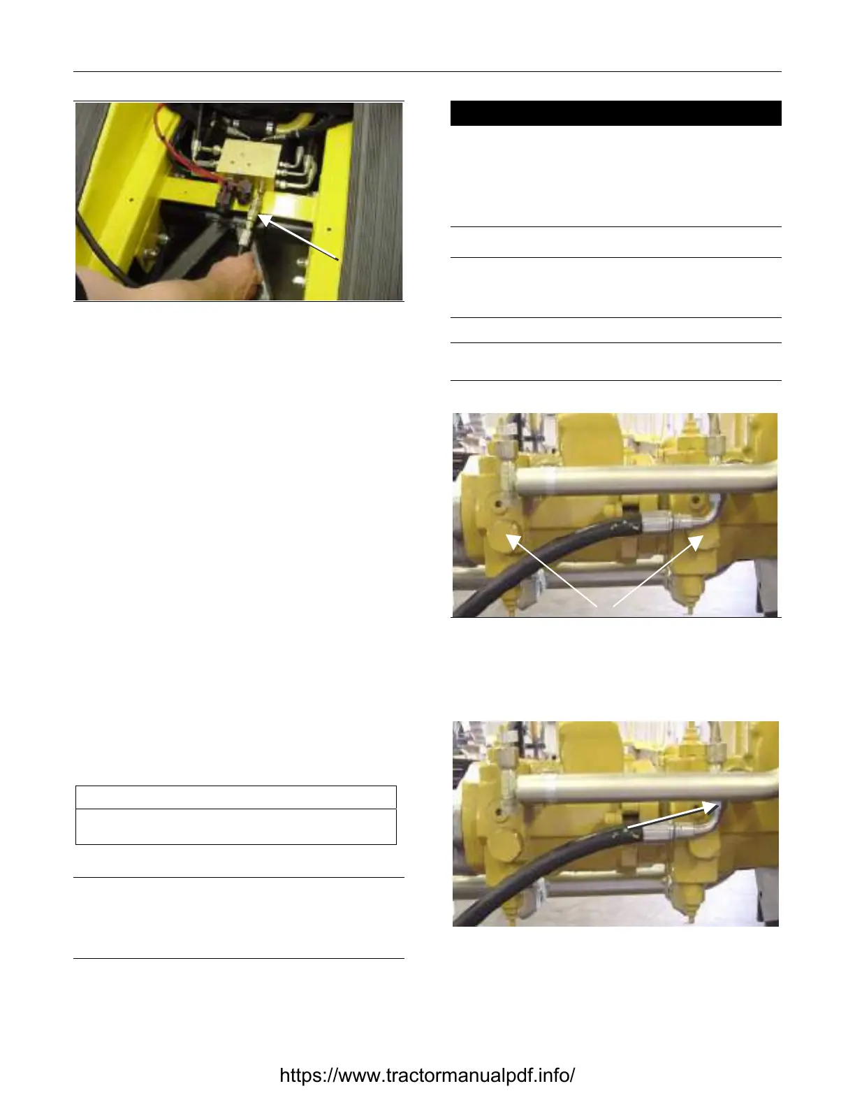
Figure 0-2 10-102
2. Attach the gauge to the pilot control manifold
test port. Located under the fuel tank, you will
not need to remove the fuel tank.
3. Start the engine.
4. Check the pressure with the engine at wide
open throttle. Make sure the engine is properly
warmed up before running wide open.
5. Turn the engine start switch to the OFF position.
6. Remove the gauge from the pilot control mani-
fold test port.
7. Install the floor pan
Charge Pressure Relief Valve Adjust-
ment
The service tools required for charge pressure relief
valve adjustment are listed in Table 0-2. Use manu-
facturer-recommended tools whenever possible.
Table 0-2
Required Tools
Combination Wrench
Socket Wrench
Note: In the following procedure, some components are
shown detached from the machine to facilitate the descrip-
tion. However, the charge pressure check is normally per-
formed from under the machine with only the center skid
plate removed.
! WARNING !
Hot oil can cause personal injury. Lower all attach-
ments and make sure the oil is cool before removing
any components or lines.
Remove the oil filler cap only when the engine is
stopped and the filler cap is cool enough to touch with
your hands.
NOTICE
Collect and contain liquids in a suitable container. Dispose
of all liquids according to local regulations and mandates.
Note: During disassembly, plug all hoses and tubes to
prevent fluid loss and contamination of the system fluids.
Figure 0-3 10-103
1. Remove belly pan and locate the charge pres-
sure relief valves on the left side of the tandem
pump.
Figure 0-4 10-104
ttach
Gauge
Remove
Hose
https://www.tractormanualpdf.info/