Rubber Track Loader
12. Undercarriage Disassembly and Assembly
12-5
Brake Removal
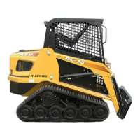
Figure 12-16 12-004
1. Locate the wheel marked C located directly be-
hind the drive sprocket. If the brake is to be re-
placed, this wheel must also be removed.
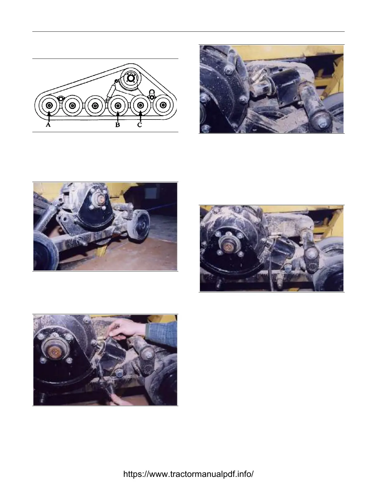
Figure 12-17 12-020
2. Remove the outside wheel marked C in step 1.
Refer to Chapter 12. Wheel Removal.
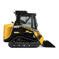
Figure 12-18 12-021
3. Remove the two bolts that fasten the brake cyl-
inder to the rail.
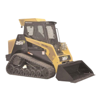
Figure 12-19 12-022
4. Move the brake cylinder out from the sprocket. If
replacing the brake cylinder, clean and discon-
nect the hoses going to the cylinder. Cap the
hoses until the new brake is ready to install.
Brake Installation
Figure 12-20 12-046
1. Using a drift pin or punch, line up the holes in
the brake cylinder with the holes in the rail. If
needed, rotate the sprocket until the cylinder
ram is between two drive pins.
https://www.tractormanualpdf.info/