Rubber Track Loader
17. Hydraulic Pressure Check & Adjustment
5
Figure 11 10-111
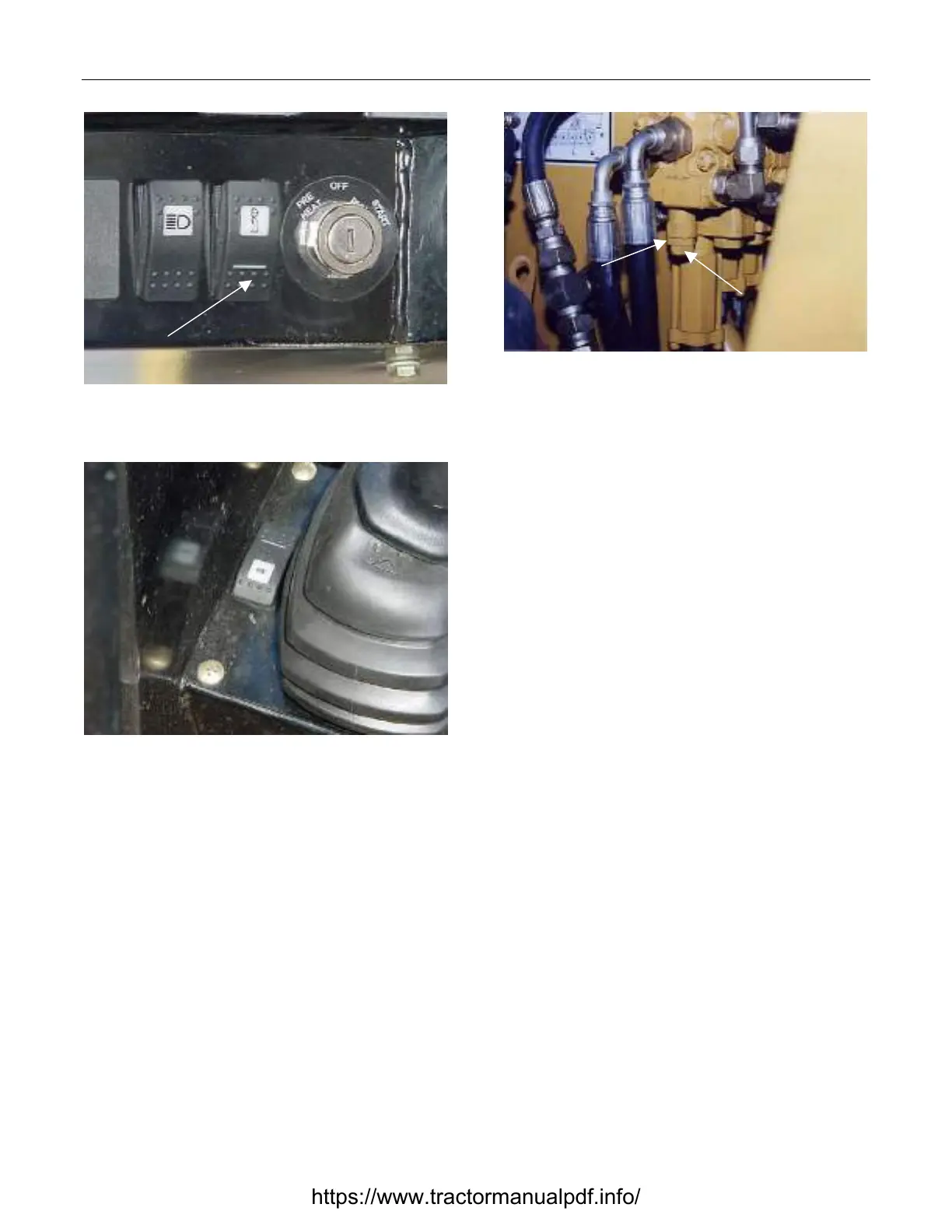
2. Make sure the auxiliary mode switch is in the
continuous (down) position.
Figure 12 10-112
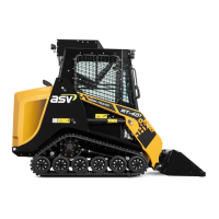
3. Engage the continuous flow switch next to the
loader control joystick. Make sure it is in the di-
rection that sends flow to the gage.
Jam Nut
Adjustment
Screw
Figure 13 10-113
4. Loosen the jam nut and turn the adjustment
screw in with an allen wrench to increase pres-
sure and turn screw out to decrease pressure.
Tighten jam nut when after adjustment has been
made.
https://www.tractormanualpdf.info/