103
7647H–AVR–03/12
Atmel ATmega16/32/64/M1/C1
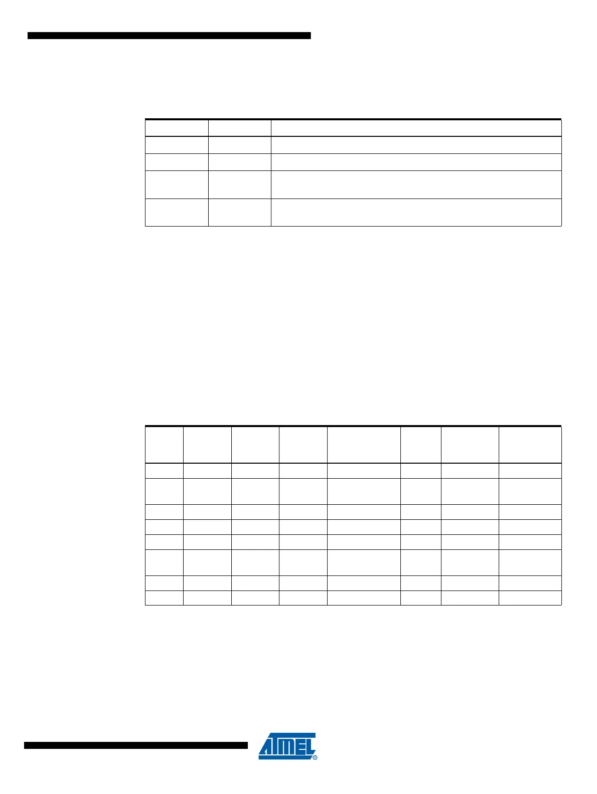
Table 12-7 shows the COM0B1:0 bit functionality when the WGM02:0 bits are set to phase cor-
rect PWM mode.
Note: 1. A special case occurs when OCR0B equals TOP and COM0B1 is set. In this case, the Com-
pare Match is ignored, but the set or clear is done at TOP. See “Phase Correct PWM Mode” on
page 98 for more details.
• Bits 3, 2 – Res: Reserved Bits
These bits are reserved bits in the ATmega16/32/64/M1/C1 and will always read as zero.
• Bits 1:0 – WGM01:0: Waveform Generation Mode
Combined with the WGM02 bit found in the TCCR0B Register, these bits control the counting
sequence of the counter, the source for maximum (TOP) counter value, and what type of wave-
form generation to be used, see Table 12-8. Modes of operation supported by the Timer/Counter
unit are: Normal mode (counter), Clear Timer on Compare Match (CTC) mode, and two types of
Pulse Width Modulation (PWM) modes (see “Modes of Operation” on page 95).
Notes: 1. MAX = 0xFF
2. BOTTOM = 0x00
Table 12-7. Compare Output Mode, Phase Correct PWM Mode
(1)
COM0B1 COM0B0 Description
0 0 Normal port operation, OC0B disconnected.
01Reserved
10
Clear OC0B on Compare Match when up-counting. Set OC0B on
Compare Match when down-counting.
11
Set OC0B on Compare Match when up-counting. Clear OC0B on
Compare Match when down-counting.
Table 12-8. Waveform Generation Mode Bit Description
Mode WGM02 WGM01 WGM00
Timer/Counter
Mode of
Operation TOP
Update of
OCRx at
TOV Flag
Set on
(1)(2)
0 0 0 0 Normal 0xFF Immediate MAX
1001
PWM, Phase
Correct
0xFF TOP BOTTOM
2 0 1 0 CTC OCRA Immediate MAX
3 0 1 1 Fast PWM 0xFF TOP MAX
4100Reserved –– –
5101
PWM, Phase
Correct
OCRA TOP BOTTOM
6110Reserved –– –
7111Fast PWMOCRATOPTOP