135
7647H–AVR–03/12
Atmel ATmega16/32/64/M1/C1
• Bit 1 – OCIE1A: Timer/Counter1, Output Compare A Match Interrupt Enable
When this bit is written to one, and the I-flag in the Status Register is set (interrupts globally
enabled), the Timer/Counter1 Output Compare A Match interrupt is enabled. The corresponding
Interrupt Vector (Table 8-2 on page 58) is executed when the OCF1A Flag, located in TIFR1, is
set.
• Bit 0 – TOIE1: Timer/Counter1, Overflow Interrupt Enable
When this bit is written to one, and the I-flag in the Status Register is set (interrupts globally
enabled), the Timer/Counter1 Overflow interrupt is enabled. The corresponding Interrupt Vector
(Table 8-2 on page 58) is executed when the TOV1 Flag, located in TIFR1, is set.
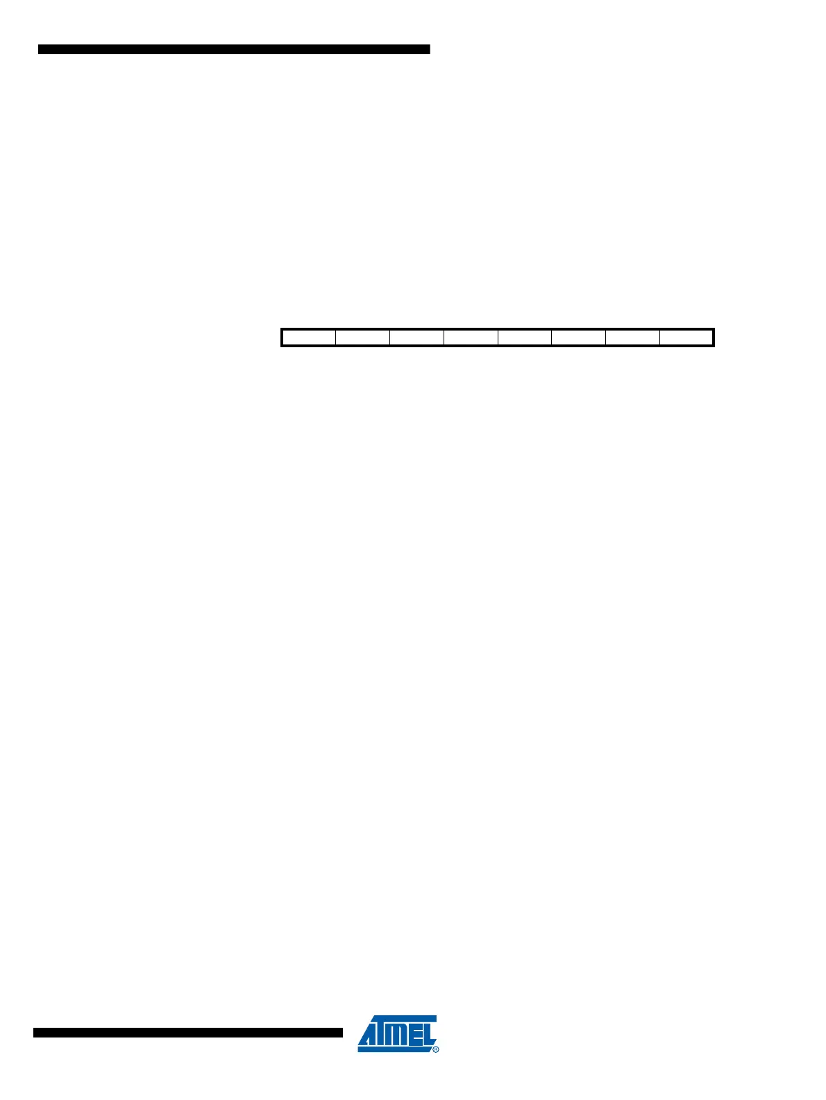
13.10.9 Timer/Counter1 Interrupt Flag Register – TIFR1
• Bit 7, 6 – Res: Reserved Bits
These bits are unused bits in the ATmega16/32/64/M1/C1, and will always read as zero.
• Bit 5 – ICF1: Timer/Counter1, Input Capture Flag
This flag is set when a capture event occurs on the ICP1 pin. When the Input Capture Register
(ICR1) is set by the WGMn3:0 to be used as the TOP value, the ICF1 Flag is set when the coun-
ter reaches the TOP value.
ICF1 is automatically cleared when the Input Capture Interrupt Vector is executed. Alternatively,
ICF1 can be cleared by writing a logic one to its bit location.
• Bit 4, 3 – Res: Reserved Bits
These bits are unused bits in the ATmega16/32/64/M1/C1, and will always read as zero.
• Bit 2 – OCF1B: Timer/Counter1, Output Compare B Match Flag
This flag is set in the timer clock cycle after the counter (TCNT1) value matches the Output
Compare Register B (OCR1B).
Note that a Forced Output Compare (FOC1B) strobe will not set the OCF1B Flag.
OCF1B is automatically cleared when the Output Compare Match B Interrupt Vector is exe-
cuted. Alternatively, OCF1B can be cleared by writing a logic one to its bit location.
• Bit 1 – OCF1A: Timer/Counter1, Output Compare A Match Flag
This flag is set in the timer clock cycle after the counter (TCNT1) value matches the Output
Compare Register A (OCR1A).
Note that a Forced Output Compare (FOC1A) strobe will not set the OCF1A Flag.
OCF1A is automatically cleared when the Output Compare Match A Interrupt Vector is exe-
cuted. Alternatively, OCF1A can be cleared by writing a logic one to its bit location.
• Bit 0 – TOV1: Timer/Counter1, Overflow Flag
The setting of this flag is dependent of the WGMn3:0 bits setting. In Normal and CTC modes,
the TOV1 Flag is set when the timer overflows. Refer to Table 13-4 on page 131 for the TOV1
Flag behavior when using another WGMn3:0 bit setting.
TOV1 is automatically cleared when the Timer/Counter1 Overflow Interrupt Vector is executed.
Alternatively, TOV1 can be cleared by writing a logic one to its bit location.
Bit 76543210
– – ICF1 – – OCF1B OCF1A TOV1 TIFR1
Read/Write R R R/W R R R/W R/W R/W
Initial Value00000000

 Loading...


