SIOL-EI8B-USER-M
94
Powered by
Version 1, May 2022
Explanation of the process data
Appendix B: Explanation of the process data
NOTE
The addresses shown in the tables in Appendix B use 0-based addressing. The Productivity Suite soft-
ware uses 1-based addressing. So, add 1 to any address in these tables when accessing these values in
Productivity Suite.
Digital Input
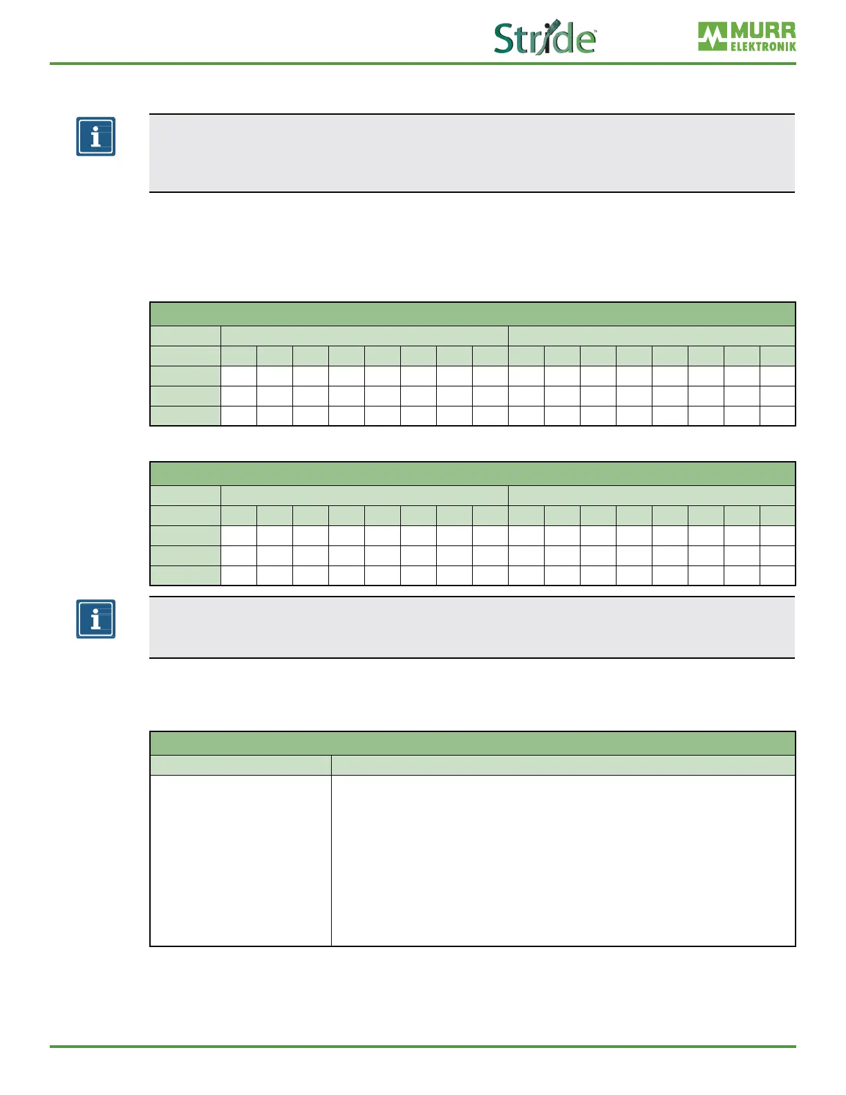
The order of the digital input data depends on the conguration parameter “Pin_Port_based_IO_Layout”.
This is explained in the following tables:
Port Based
Port-Based Digital Input
Byte 1 0
Bit 7 6 5 4 3 2 1 0 7 6 5 4 3 2 1 0
Port
X7 X7 X6 X6 X5 X5 X4 X4 X3 X3 X2 X2 X1 X1 X0 X0
Pin
2 4 2 4 2 4 2 4 2 4 2 4 2 4 2 4
Channel
17 07 16 06 15 05 14 04 13 03 12 02 11 01 10 00
Pin Based
Pin-Based Digital Input
Byte 1 0
Bit 7 6 5 4 3 2 1 0 7 6 5 4 3 2 1 0
Port
X7 X6 X5 X4 X3 X2 X1 X0 X7 X6 X5 X4 X3 X2 X1 X0
Pin
2 2 2 2 2 2 2 2 4 4 4 4 4 4 4 4
Channel
17 16 15 14 13 12 11 10 07 06 05 04 03 02 01 00
NOTE
The tables for Port and Pin Based are also applicable to Digital Input Qualier, Digital Output Qualier
and Digital Output.
B.1. System Status
The system state bit string provides information about the entire device.
System Status Bit String
Byte Description
0–3
Bit 0: Bus/sensor supply undervoltage
Bit 1: Actuator supply undervoltage Bit 3: External error
Bit 4: At least one channel has a sensor short circuit
Bit 5: At least one channel has an actuator short circuit
Bit 6: At least one channel has an actuator warning
Bit 7: At least one analog channel has an error
Bit 8: Internal communication error
Bit 9: At least one IO-Link channel has an error (except wire break)
Bit 10: Bus/sensor supply overvoltage
Bit 11: Actuator supply overvoltage
Bit 12: At least one IO-Link channel has a wire break
Bit 13–31: Reserved, set to 0