SIOL-EI8B-USER-M
6
Description Powered by
Version 1, May 2022
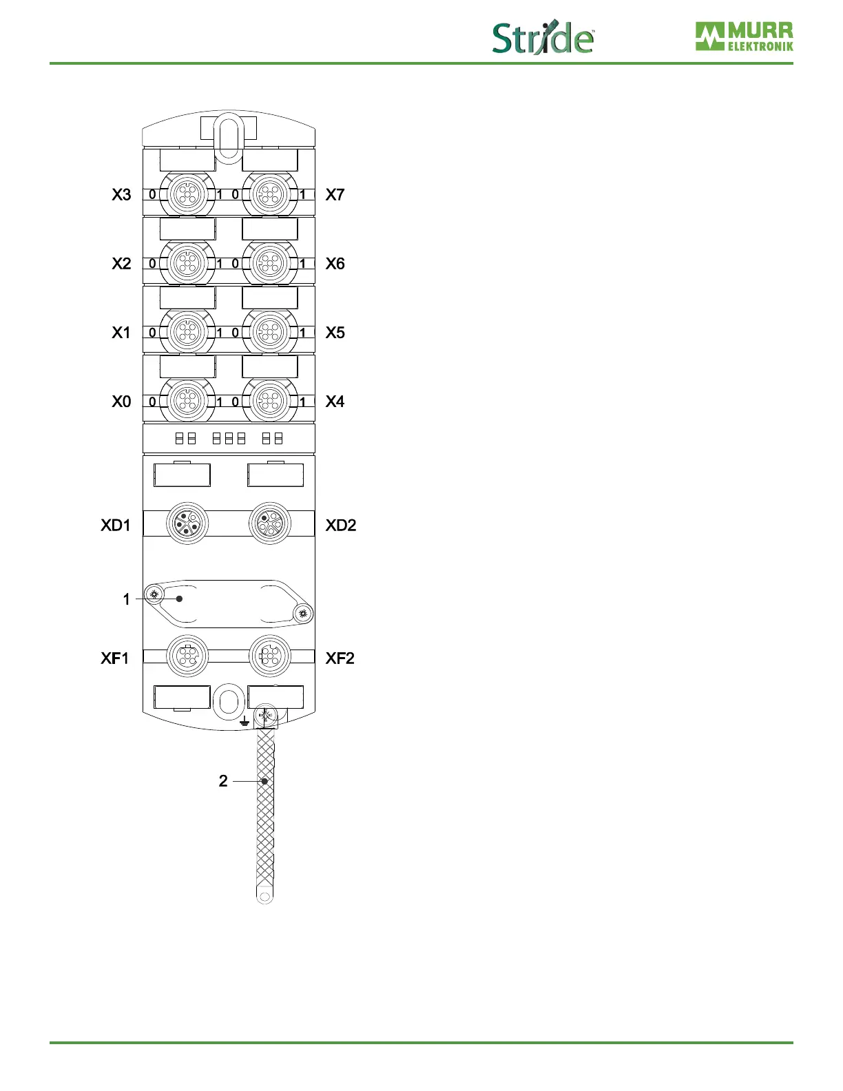
3.1.2. Module structure
X0–X7 Digital inputs and outputs or IO-Link,
M12, A-coded
0 Channel corresponds to pin 4
1 Channel corresponds to pin 2
XD1 Power supply POWER IN, M12,
L-coded, 5-pin
XD2 Power supply POWER OUT, M12,
L-coded, 5-pin
1 Rotary switch
Fig. 3-1: Module structure
XF1 Ethernet port 1, M12, D-coded
XF2 Ethernet port 2, M12, D-coded
2 Ground strap for functional ground