SIOL-EI8B-USER-M
9
Description Powered by
Version 1, May 2022
3.1.5. Rotary switch settings
NOTE
In the default state, the rotary switches are set to 000, DHCP enabled.
NOTE
A unique IP address must be assigned to each device in the network.
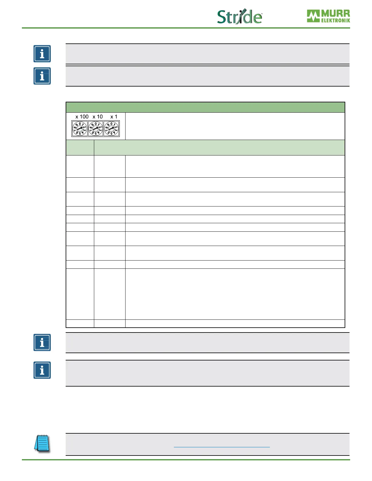
Setting the IP Address on the Rotary Switches
Address range: 1–999
x1 Rotary switch 9ones)
x10 Rotry switch (tens)
x100 Rotary switch (hundreds)
Position/
Range
Description
0 DHCP
Request the IP addresses via DHCP (can be changed to BOOTP via the WebUI or Explicit Messaging)
◼ After factory reset: DHCP
◼ The network parameters have been saved previously: The parameters saved last are used.
1–254
IP address
Byte 4
The last octet of the IP address (set via DHCP or WebUI) is overwritten by the DIP switch setting and applied.
The default IP address subnet is 192.168.1.xxx
255
Last saved
IP address
The IP address saved last is used. (192.168.1.6 by default)
256–776 Reserved
777 Fixed IP The IP address is set STATIC at 192.168.100.177.
778–912 Reserved
913
Deactivate
web server
Disables the web server and TCP port 80. Only the WebUI is disabled.
914
Reactivate
web server
WebUI is enabled again.
915–978 Reserved
979 Factory reset
Sequence:
1 | Disconnect module from power supply.
2 | Set switch position 979.
3 | Supply module with power.
4 | Wait until SF LED changes from ashing green to solid green.
5 | Disconnect module from power.
6 | Switch position to 000 or any other desired position.
7 | Supply module with power.
980–999 Reserved
NOTE
The saved default IP address is 192.168.1.6.
NOTE
The IP address parameters are stored for all switch settings. This must be taken into account in
particular with the switch setting 0.
Setting an address
1. Remove the rotary switch cover.
2. Set the three rotary switches.
3. Carefully replace the rotary switch cover.
The tightening torques can be found in Section 5.4.2, “Rotary switch cover”.