3-20 Basic Installation MN1902
3.6 Regen eration resistor (Dynamic Brake resistor)
The 2.5A and 5A FlexDrive
II
both have an internally fitted regeneration resistor *. For 7.5A,
15A, 20A and 27.5A FlexDrive
II
, an external regeneration resistor must be installed to
dissipate excess power from the internal DC bus during motor deceleration.
Suitable regeneration resistors are listed in section A.1.7.
WARNING: A regeneration resistor may generate enough heat to
ignite combustible materials. To avoid fire hazard,
keep all combustible materials and flammable vapors
away from the resistors.
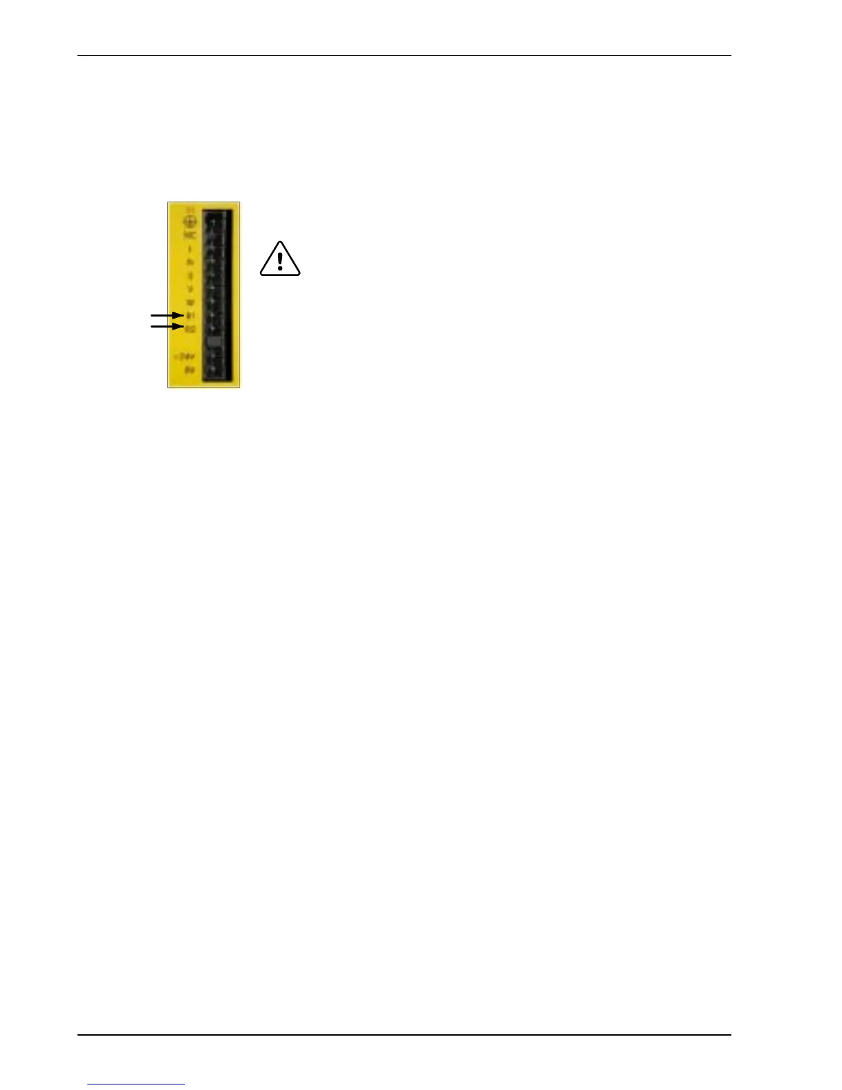
The regeneration resistor should be mounted near the top of an enclosure
to maximize heat dissipation. When the motor regenerates, the yellow
DB On LED on the front panel of the FlexDrive
II
will illuminate.
* If required by the application, additional external resistors connected to R1 and R2 will be
connected in parallel with the internal resistor .
3.6.1 Controlling regeneration
Some regeneration resistor assemblies include an overload switch to indicate when too much
power is being dissipated by the resistor. This switch can be wired to a digital input on the
FlexDrive
II
. Using the W orkBench v5 Digital I/O tool, the input can be configured to be the
brake trip input. This allows the FlexDrive
II
to respond to resistor overload conditions.
The Mint keyword DBEXTTRIPINPUT can also be used to configure a digital input for this
purpose. On three-phase FlexDrive
II
models, the operation of the regeneration resistor can be
controlled by further Mint keywords. These also begin with the letters DB..., for example
DBEXTPEAKPOWER. See the Mint help file for details.
R1
R2