Basic Installation 3-15MN1902
3.5 Motor connections
The motor can be connected directly to the FlexDrive
II
or through a motor contactor
(M-Contactor).
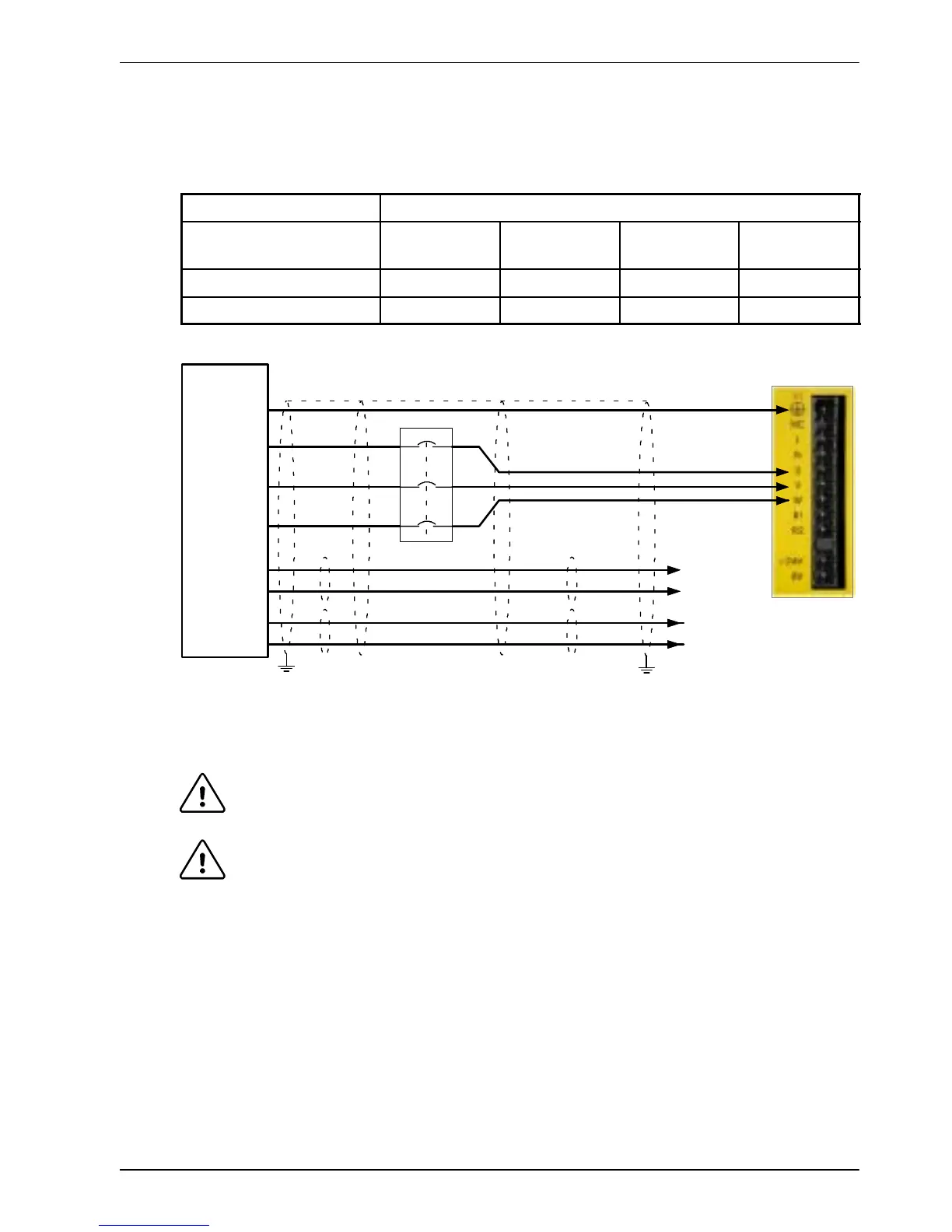
Location
Connector X1 / X1A
Part number
FDH1A...
FPH1A...
FDH2A...
FPH2A...
FDH2A15...
FPH2A15...
FDH4A...
FPH4A...
Nominal output voltage 160VDC 320VDC 320VDC 565/650V
Output voltage range 135-176VDC 306-350VDC 258-355VDC 254- 746VDC
See
section
3.5.4
V
W
U
Motor
To earth/ground outer shield, use 360° clamps connec ted to back plane
Thermal
switch
A
B
Brake
(if present)
C
D
See
section
3.5.5
Unshielded
lengths shoul d be
as short as
poss ible.
Optional motor
circuit contac tors
Figure 7 - Motor connections
CAUTION: Do not connect supply power to the FlexDrive
II
UVW outputs. The
FlexDrive
II
might be damaged.
CAUTION: The motor leads U, V and W must be connected to their corresponding U,
V or W terminal on the motor. Misconnection will result in uncontrolled
motor movement.
The motor power cable must be shielded for CE compliance. The connector or gland used at
the motor must provide 360 degree shielding. The maximum recommended cable length is
30.5m (100ft).
Note: For CE compliance the motor earth/ground should be connected to the drive
earth/ground.
 Loading...

