4-4 Input / Output MN1902
4.2.2 Relay output - X3
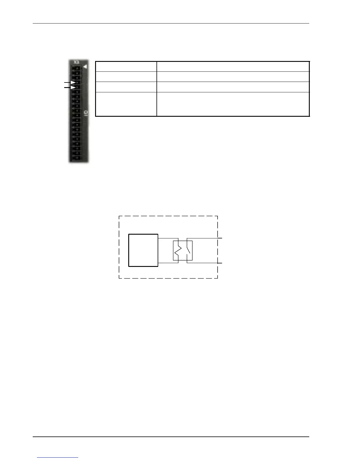
Location Connector X3, pins 4 (+) & 5 (-)
Name General purpose relay
Mint keyword RELAY
Description Relay switch contacts controlled by Mint, rated at 1A,
30VDC. Normally closed.
Update interval: Immediate
The factory preset assignment for the relay is as the global error output signal
(see the Mint keyword GLOBALERROROUTPUT). When an error occurs the relay
is de-energized and the normally closed relay contacts are opened.
When the error is cleared, the relay is re- energized and the contacts are
closed. The relay can be also be controlled directly by the Mint keyword RELAY.
When the relay is de-energized (RELAY=_off) the contacts open.
An axis can use the relay as its drive enable output signal. This can be configured in
W orkBench v5 or by using the Mint keyword DRIVEENABLEOUTPUT. This prevents
access by RELAY, but means that the relay can be used to monitor the state of the
DRIVEENABLE keyword. See the Mint help file for details.
Internal relay
FlexDrive
II
Relay +
Pin 4
Relay -
Pin 5
Control
circuitry
Figure 25 - Relay contact outputs
4
5
 Loading...

