Input / Output 4-17MN1902
4.4.6 Connecting Baldor HMI Operator Panels
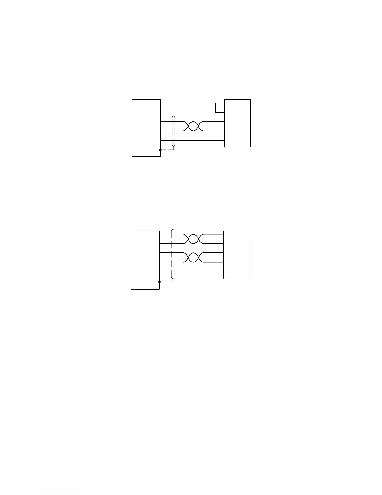
Baldor HMI Operator Panels use a 15-pin male D-type connector (marked PLC PORT), but
the FlexDrive
II
connector X6 is a 9-pin male D-type connector. If you do not require hardware
handshaking then use the connections shown in Figure 35:
7RTS
8CTS
3TXD
2RXD
5GND
1
RXD 2
TXD 3
GND 5
Baldor HMI
PLC PORT
FlexDrive
II
X6
Twisted pai r
Figure 35 - Cable wiring if hardware handshaking is not required
If hardware handshaking is required then use the connections shown in Figure 36:
7RTS
8CTS
3TXD
2RXD
5GND
1
RXD 2
TXD 3
GND 5
Baldor HMI
PLC PORT
FlexDrive
II
X6
CTS 11
RTS 10
Twisted pai r
Figure 36 - Cable wiring if hardware handshaking is required
 Loading...

