4-14 Input / Output MN1902
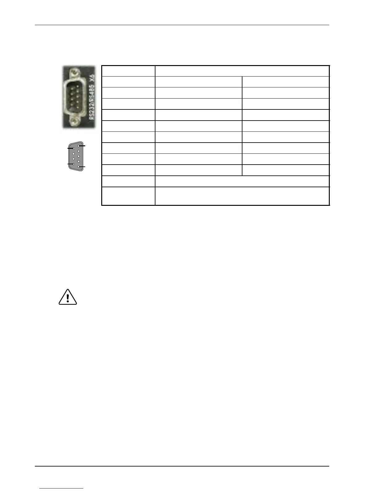
4.4.3 Serial port - X6
Location Connector X6
Pin RS232 name RS485 / RS422 name
1 (NC) (NC)
2 RXD RX- (input)
3 TXD TX- (output)
4 (NC) (NC)
5 0V GND 0V DGND
6 (NC) (NC)
7 RTS TX+ (output)
8 CTS RX+ (input)
9 (Do not connect! See caution below)
Description RS232 or RS485 / RS422 connections on a single
9- pin female D-type connector
Connector X6 is a 9-pin male D- type connector . This port is configurable as either RS232 or
4- wire RS422 / RS485, using front panel DIP switch number 10 (see section 3.9.6). The Mint
keyword SERIALBAUD is used to configure the port and is explained in the M int help file. See
also sections 4.4.4 and 4.4.5. The port is fully ESD protected to IEC 1000-4- 2 (15kV).
When using RS485 / RS422 mode, front panel DIP switch number 6 may be used to connect
an internal 120Ω termination resistor between the RX+ and RX- signals. Switch 6 should
remain in the Off position when using RS232.
CAUTION: Pin 9 is used to carry +8V for powering certain Baldor keypad peripherals.
Ensure that pin 9 is not connected to earth/ground or to equipment that
could be damaged by the +8V supply.
1
5
6
9

 Loading...
