4-18 Input / Output MN1902
4.5 Connectio n summary - minimum system wiring
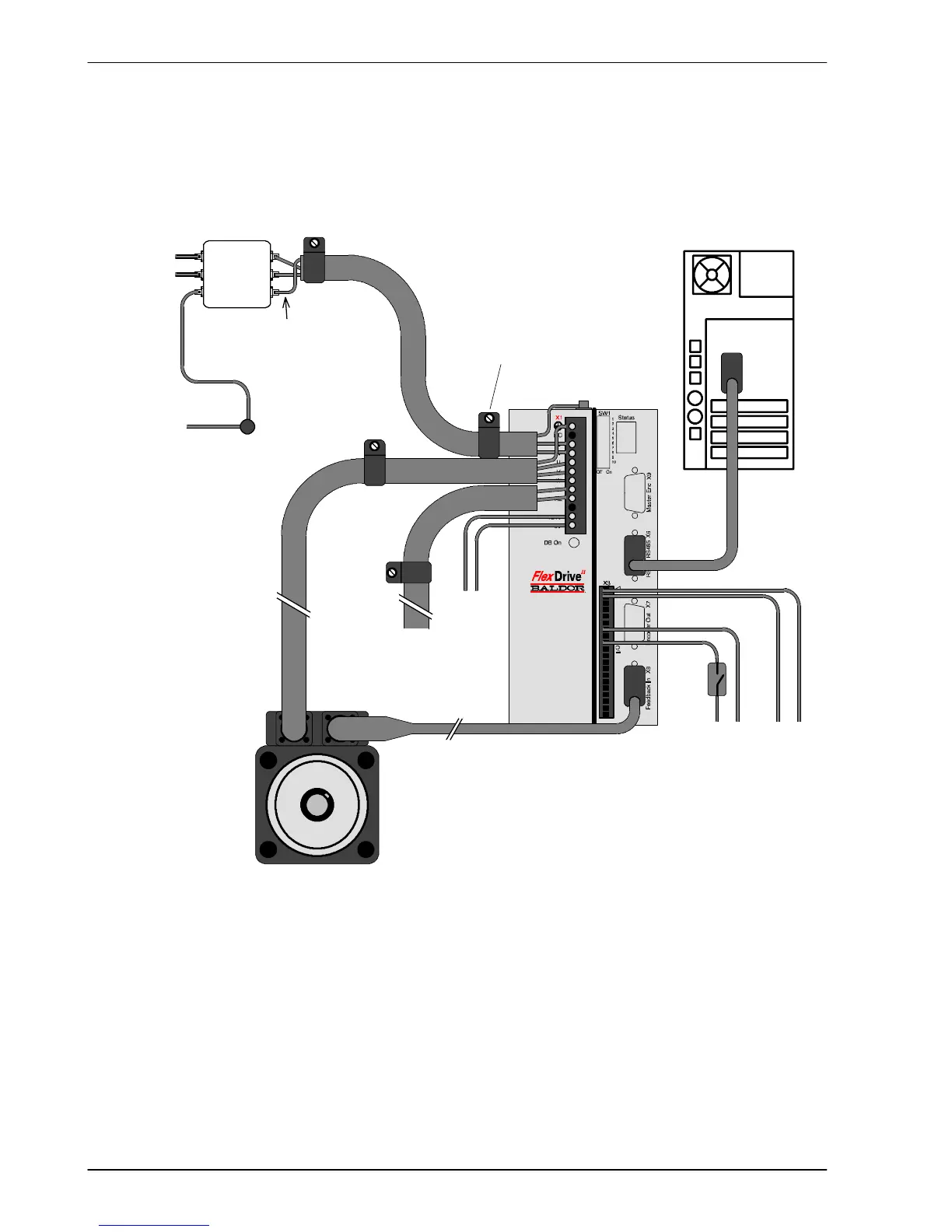
As a guide, Figure 37 shows an example of the typical minimum wiring required to allow the
FlexDrive
II
to control a motor.
COM
Host PCAC power
Motor
power
UVW
Serial communicati on
To regen
resistor
(Dynamic
brake)**
Customer
supplied
24V**
Motor
Drive
enable
switch
+24V
+24V 0V
** Model shown: FDH2A07TR-RN23:
This model requires an external regeneration resistor and c ustomer s upplied 24V supply - see sections 3.6 and 3.4.7.
Some models contain an internal 24V supply and/or an internal regeneration resistor.
Command input may be di fferential (shown) or single ended. See section 4.2.1.
Motor represents a typical Bal dor BS M motor. Linear motors may also be controlled by FlexDrive
II
.
Shield earth/ground clamps are not s upplied.
0V
Filter
L
N
PE
L
N
E
Star
point
If the fil ter has no output
earth/ground terminal, earth
wire may be c onnected
directly to the star poi nt.
AC
power
in
L
N
E
Shield earth/ground clamp
attached to enclosure bac kplane
Command
input
Figure 37 - Example minimum system wiring
 Loading...

