4-6 Input / Output MN1902
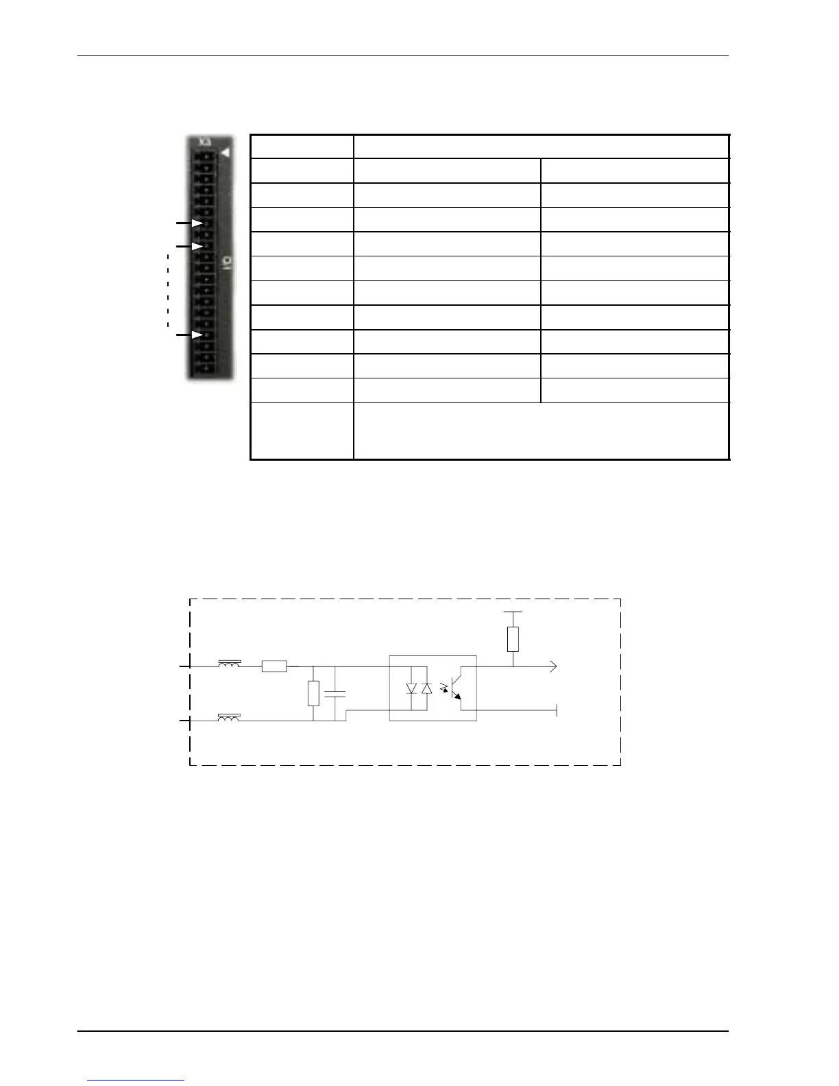
4.3.1 Digital inputs - X3
Location Connector X3
Pin Name Mint keyword
9 Drive Enable -
10 DIN0 INX.0
11 DIN1 INX.1
12 DIN2 INX.2
13 DIN3 INX.3
14 DIN4 INX.4
15 DIN5 INX.5
16 DIN6 INX.6
17 DIN7 INX.7
Description Eight general-purpose optically isolated AC digital inputs.
One committed drive enable input (Drive Enable).
Sampling interval: 2ms
The digital inputs DIN0 - DIN7 can be read individually using the associated Mint keyword INX
(for example INX.7) and can be configured for many user definable functions. Each input
circuit contains an opto-isolator as shown in Figure 26. Inputs DIN4 and DIN5 can also be
used as fast inputs - see section 4.3.4. The state of each digital input is displayed in the
W orkBench v5 Spy window.
Active high: DINx=+24VDC (±20%)
CREF=0V
CREF
Pin 7
DIN0
Pins 10
4k7
1k 0.1µF
NECPS2565
DGND
Mint
INX.0
10k
Vcc
FlexDrive
II
Active low: DINx=0V
CREF=+24VDC (±20%)
Figure 26 - X3 digital input circuit - DIN0 shown
9
17
CREF 7
 Loading...

