3-22 Basic Installation MN1902
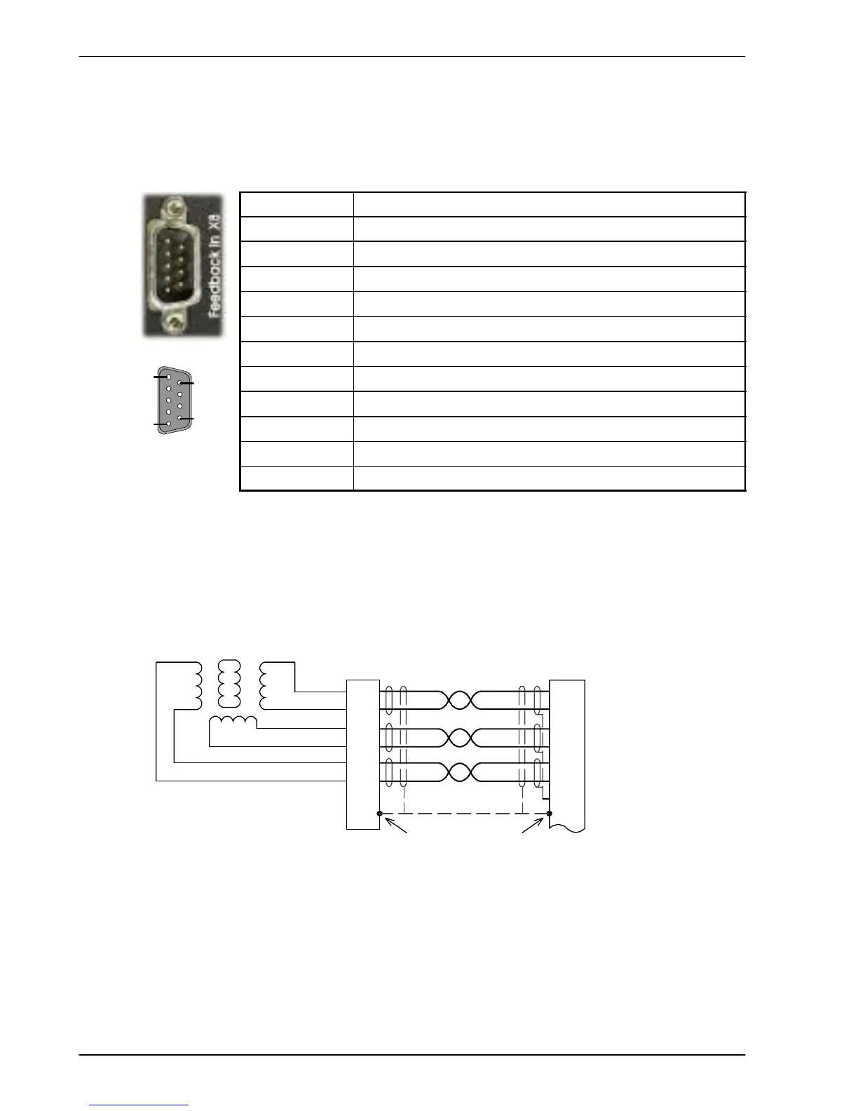
3.7.1 Resolver option - X8
The resolver connections are made using the 9-pin D-type male connector X8. Twisted pair
cables must be used for the complementary signal pairs e.g. SIN+ and SIN-. The overall cable
shield (screen) must be connected to the metallic shell of the D-type connector.
Location
Connector X8, 9-pin D-type male connector
Pin Resolver function
1 REF+
2 COS+
3 SIN+
4 (NC)
5 Analog Ground
6 REF-
7 COS-
8 SIN-
9 Chassis Ground
Description Resolver input with 14-bit resolution
The resolver input is used to create an encoder signal inside the FlexDrive
II
. This provides the
FlexDrive
II
with an equivalent resolution of 4096 pulses per revolution (ppr), although this can
be reconfigured in the W orkBench v5 Commissioning Wizard to provide 1024 ppr. The
FlexDrive
II
provides an input accuracy of ±3 counts. When used with a typical Baldor BSM
series resolver motor the combined accuracy is ±11 counts (calculated with the input
equivalent resolution set to the factory preset value of 4096 ppr).
1
6
2
7
3
8
5
R2
R1
S2
S4
S1S3
X8
SIN+
SIN-
COS+
COS-
REF+
REF-
AGND
+
Twisted
pairs
Baldor motor
resolver connector
5
6
3
4
1
2
Connect overall shield
to connector backshells.
Connect internal
shields to AGND.
+
+
Figure 11 - Resolver cable connections
1
5
6
9