Basic Installation 3-7MN1902
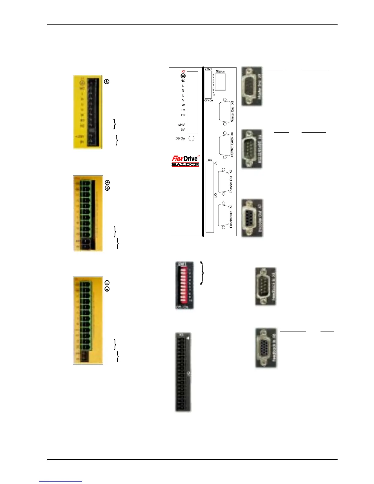
3.3 Connector locations
1 AIN0+ (Command+)
2 AIN0- (Command-)
3AGND
4 Relay +
5 Relay -
6UserV+
7 CREF
8CGND
9 Drive Enable
10 DIN0
11 DIN1
12 DIN2
13 DIN3
14 DIN4 (Pulse)
15 DIN5 (Direction)
16 DIN6
17 DIN7
18 DOUT0
19 DOUT1
20 DOUT2
1 CHA+
2 CHB+
3 CHZ+
4 (NC)
5DGND
6 CHA-
7 CHB-
8 CHZ-
9 (NC)
Encoder Pulse & Dir.
1 CHA+ Pulse+
2 CHB+ Dir.+
3 CHZ+ (NC)
4 (NC) (NC)
5DGND (NC)
6 CHA- Pulse GND
7 CHB- Dir. GND
8 CHZ- (NC)
9+5V (NC)
RS232 RS485/422
1 (NC) (NC)
2RXD RX-
3TXD TX-
4 (NC) (NC)
5 0V GND 0V DGND
6 (NC) (NC)
7 RTS TX+
8CTS RX+
9 (NC - see secti on 4.4.3)
1REF+
2COS+
3SIN+
4 (NC)
5AGND
6REF-
7COS-
8SIN-
9 Chassis
1 Node
2 number
3 selection
4
5 (Reserved)
6Hold
7 Offset tuning
8 Enabl e
9 (Reserved)
10 RS232/RS 485
X3 General I/O
X6 RS232/RS485
X7 Encoder Out
X8 Feedback In
Resolver option
Encoder options
X1 / X1A Power
Single-phase models
Three-phase models, 230-460V
Earth
NC (NC)
LACLine
N AC Neutral
U Motor U
V Motor V
W Motor W
R1 Regen Resistor
R2 (Dynamic Brake)
- (NC)
+24V Customer
0V s upplied 24V
(FDHxxxxxx-xxx3/
FPHxxxxxx-xxx3)
Options:
If there are other connectors on the
front panel of your FlexDriv e
II
, then an
option i s fitted. See the other manuals
supplied with your FlexDrive
II
.
Earth
Earth
L1 AC Phase 1
L2 AC Phase 2
L3 AC Phase 3
U Motor U
V Motor V
W Motor W
R1 Regen Resistor
R2 (Dynamic Brake)
+24V Customer supplied 24V
0V (FDH4xxxxx-xxx3/
FPH4xxxxx-xxx3
X9 Master Encoder
SW1 DIP switches
Earth
Earth
L1 AC Phase 1
L2 AC Phase 2
L3 AC Phase 3
U Motor U
V Motor V
W Motor W
Vcc+ (NC)*
Vcc- (NC)*
R1 Regen Resistor
R2 (Dynamic Brake)
+24V Customer supplied 24V
0V (FDH2xxxxx-xxx3/
FPH2xxxxx-xxx3
Tightening torque for terminal bloc k
connec tions is 0.5-0.6Nm (4.4-5.3 lb-in)
* Warning! High voltages are present on
terminals labeled Vcc+ and Vcc-. Do not
make a connection to these terminals.
(NC) = Not Connected. Do not make a
connec tion to this pin.
Three-phase models, 230V
Incremental EnDat
1 CHA+ Data+
2 CHB+ Data-
3 CHZ+ (NC)
4 Hall U+ +5V
5HallU- DGND
6 CHA- Shield
7 CHB- Cos B-
8 CHZ- (NC)
9 Hall W+ Clock-
10 Hall V+ Clock+
11 +5V DGND
12 (NC) Sin A-
13 DGND Sin A+
14 Hall W- Cos B+
15 Hal l V- (NC)
 Loading...

