3-24 Basic Installation MN1902
3.7.2 Encoder option - X8
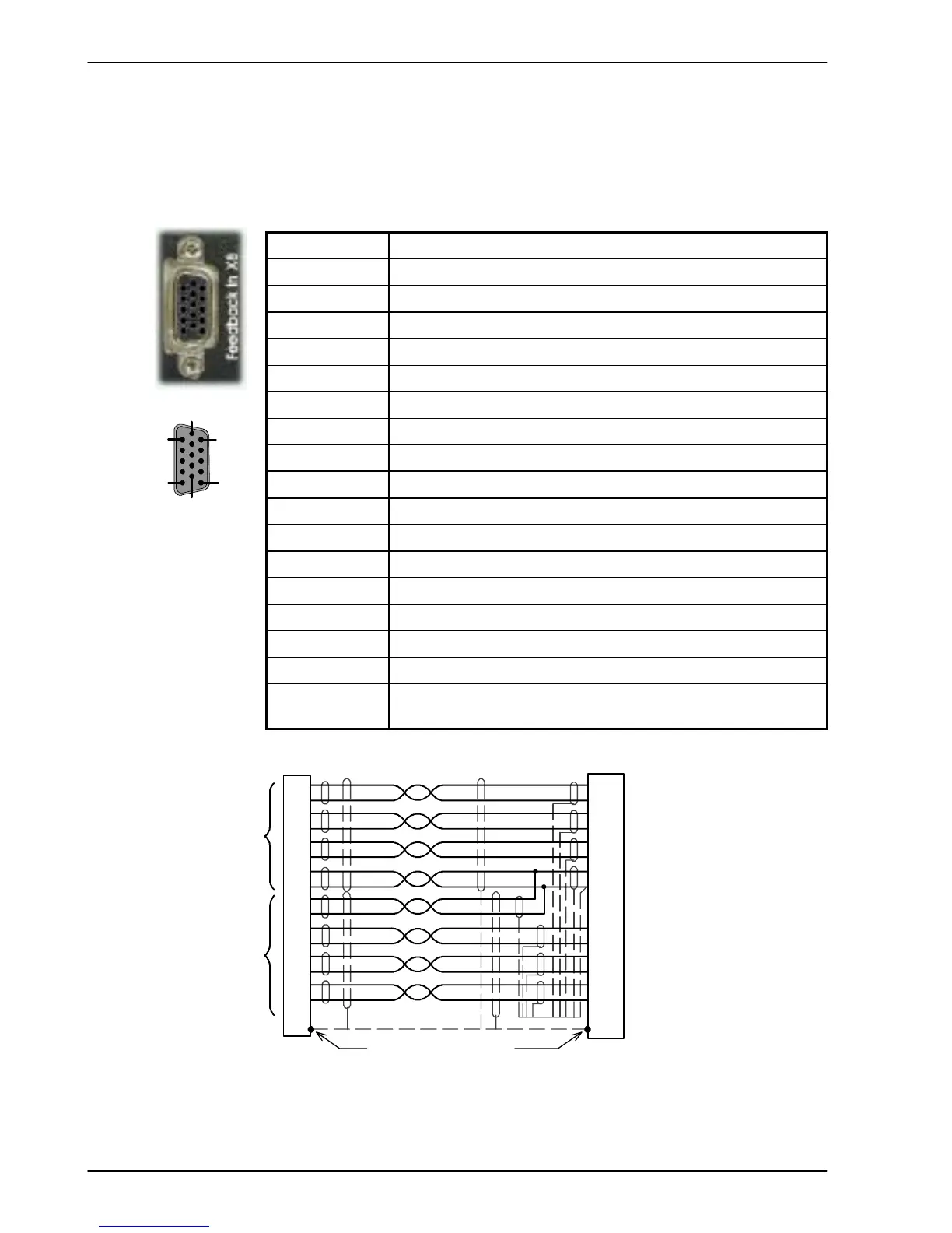
The encoder connections (ABZ channels and Hall signals) are made using the 15- pin D-type
female connector X8. Twisted pair cables must be used for the complementary signal pairs
e.g. CHA+ and CHA-. The overall cable shield (screen) must be connected to the metallic
shell of the D-type connector.
Location
Connector X8, 15-pin D-type female connector
Pin Encoder function
1 CHA+
2 CHB+
3 CHZ+
4 Hall U+
5 Hall U-
6 CHA-
7 CHB-
8 CHZ-
9 Hall W+
10 Hall V+
11 +5V out
12 (NC)
13 DGND
14 Hall W-
15 Hall V-
Description Commutating (UVW) encoder input, non- isolated. Pin 11
provides +5V for encoders requiring power (200mA max)
CHA+
CHA-
CHB+
CHB-
+5V
DGND
1
6
2
7
3
8
11
X8
CHZ+ (INDEX)
CHZ- (INDEX)
4
5
9
14
10
15
13
Hall U+
Hall U-
Hall W+
Hall W-
Hall V+
Hall V-
12 (NC)
Hall
Feedback
Connect overall shield
to connector backshells.
Twisted pai rs
Connect internal
shields to DGND.
Encoder
Feedback
Motor
Figure 13 - Encoder cable c onnections - rotary motors
1
5
15
6
11
10
 Loading...

