Basic Installation 3-25MN1902
3.7.2.1 Encoder cable pin configuration - rotary motors
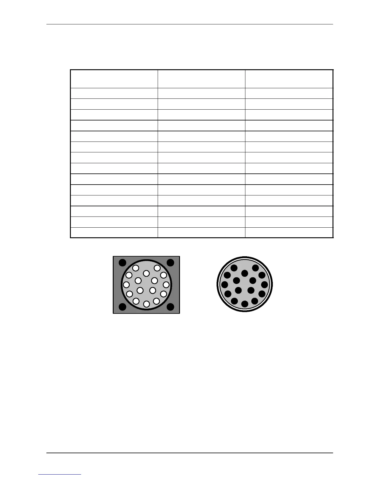
Figure 14 shows the pin configuration for a typical Baldor encoder feedback cable, part
number CBL030SF-KPCEA3.
Signal na me
FlexDrive
II
X8 pin
Motor / cable
pin
CHA+ 1 3
CHA- 6 4
CHB+ 2 5
CHB- 7 6
CHZ+ 3 7
CHZ- 8 8
Hall U+ 4 10
Hall U- 5 11
Hall V+ 10 12
Hall V- 15 13
Hall W+ 9 14
Hall W- 14 15
+5V 11 1
DGND 13 2
Motor enc oder c onnector
(male)
Pins 9 and 16
are not
connec ted
1
2
3
4
5
6
7
8
9
10
11
12
13
1415
16
Cable connector end view
(female)
1
2
3
4
5
6
7
8
9
10
11
12
13
14 15
16
Figure 14 - Baldor rot ary motor encoder ca ble pin configuration
The maximum recommended cable length is 30.5m (100ft).

 Loading...
