EasyManuals Logo

Baldor Flex+DriveII Installation Manual

Baldor Flex+DriveII
126 pages
To Next Page IconTo Next Page
To Previous Page IconTo Previous Page
Page #40 background imageLoading...
Page #40 background image
3-26 Basic Installation MN1902
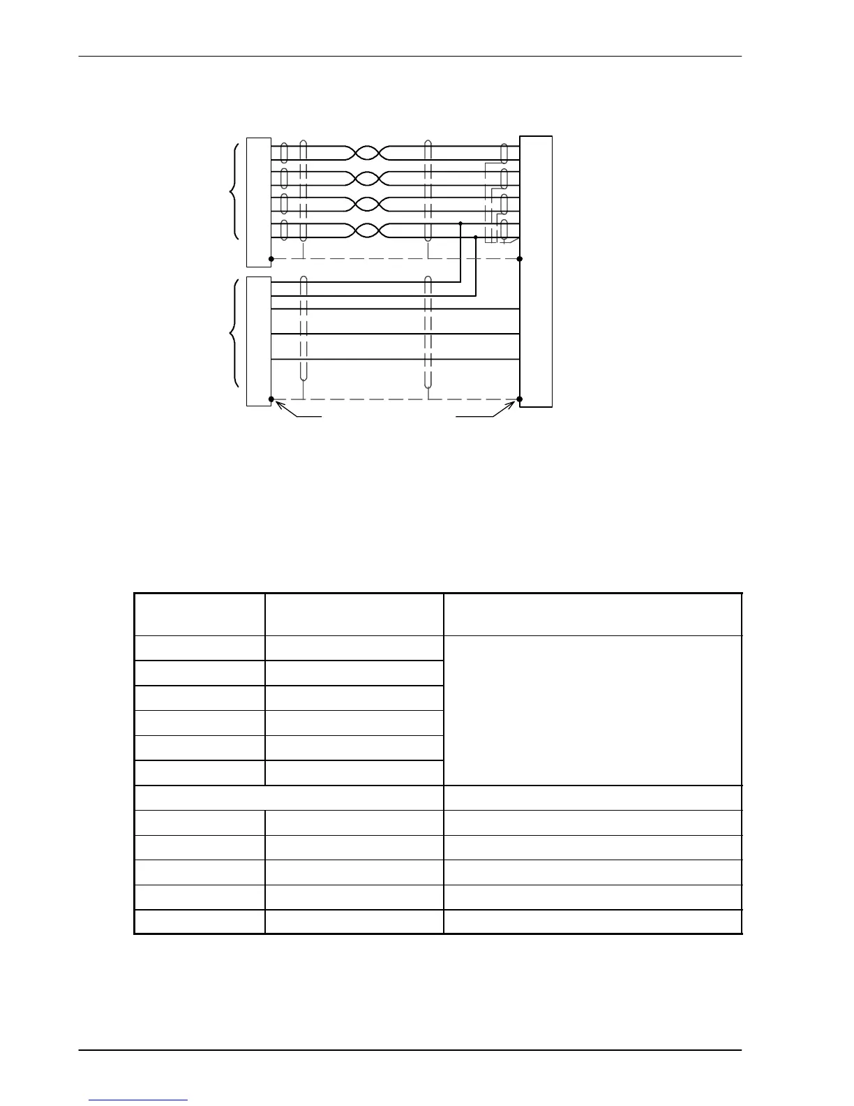
3.7.2.2 Encoder cable connections - linear motors
CHA+
CHA-
CHB+
CHB-
+5V
DGND
1
6
2
7
3
8
11
X8
Encoder
Feedback
CHZ+ (INDEX)
CHZ- (INDEX)
4
5
9
14
10
15
13
Hall U+
Hall U-
Hall W+
Hall W-
Hall V+
Hall V-
12 (NC)
Hall
Feedback
Connect ove rall shield to
connec tor backshells.
Twisted pai rs
Connect internal
shields to DGND.
Leave pi ns
5, 12, 14, 15
unconnec ted
Motor
Figure 15 - Encoder cable c onnections - linea r motors
3.7.2.3 Encoder cable pin configuration - linear motors
Linear motors use two separate cables (encoder and Hall). The cores of these two cables
must be wired to the appropriate pins of the 15- pin D-type mating connector (supplied):
Signal na me
FlexDrive
II
X8 pin
Encoder cable internal wire colors
CHA+ 1
CHA- 6
CHB+ 2
Please refer to MN1800 Linear Motors
CHB- 7
P
l
e
a
s
e
r
e
f
e
r
t
o
M
N
1
8
0
0
L
i
n
e
a
r
M
o
t
o
r
s
Installation & Operating Manual for details.
CHZ+ 3
CHZ- 8
Baldor Hall cable internal wire colors
Hall U+ 4 White
Hall V+ 10 Red
Hall W+ 9 Black
+5V 11 Brown
Hall GND 13 Green

Table of Contents

Other manuals for Baldor Flex+DriveII

Questions and Answers:

Question and Answer IconNeed help?

Do you have a question about the Baldor Flex+DriveII and is the answer not in the manual?

Baldor Flex+DriveII Specifications

General IconGeneral
BrandBaldor
ModelFlex+DriveII
CategoryServo Drives
LanguageEnglish

Related product manuals