4-2 Input / Output MN1902
4.2.1 Analog input - X3 (command)
Location
Connector X3, pins 1-3
(Mating connector:
Phoenix MINI-COMBICON MC 1.5/20-ST-3,5)
Name AIN0
Mint keyword ADC.0
Description Single ended or differential input.
Common mode voltage range: ±10VDC.
Resolution: 14-bit with sign (accuracy ±4.9mV)
Common mode rejection: 40dB
Input impedance: >5kΩ
Sampling interval: 500µs - Software (Mint programs)
125µs - High speed command
reference signal
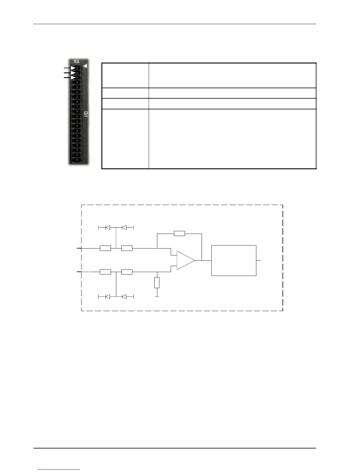
Analog input X3 can be connected as either a differential or a single ended input as shown in
Figure 22.
AIN0-
Pin 2
AIN0+
Pin 1
10k
LF412
AGND
Mint
ADC.0
FlexDrive
II
10k
10k
10k
-15V+15V
-15V+15V
20k
-
+
20k
Low pass fi lter &
level correction
(inverts s ignal)
Figure 22 - AIN0 analog input circuit
1
2
3