4-10 Input / Output MN1902
4.4 Other I/O
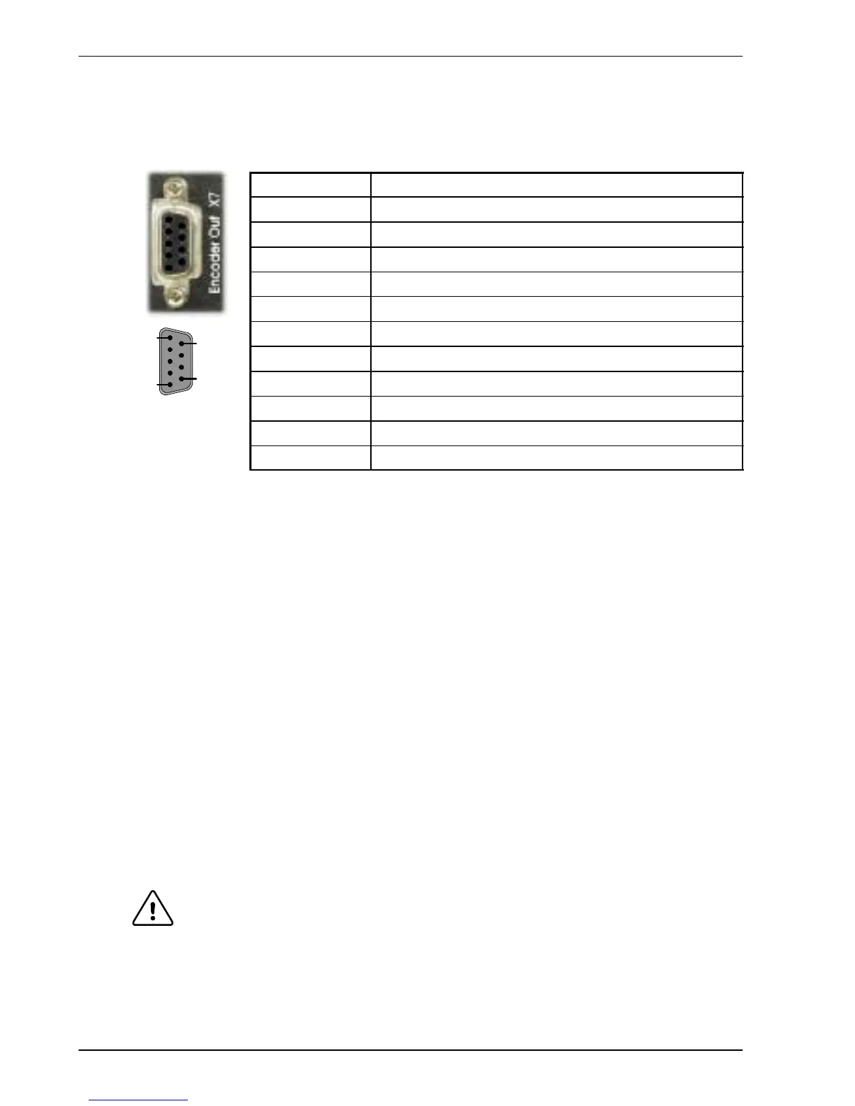
4.4.1 Encoder output - X7
Location Connector X7
Pin Name
1 CHA+
2 CHB+
3 CHZ+
4 (NC)
5 DGND
6 CHA-
7 CHB-
8 CHZ-
9 (NC)
Description Encoder output on a 9-pin female D-type connector
This output can be used for position feedback to a host positioner, or in master/slave situations
where the axis movement can be transmitted to another controller or FlexDrive
II
.Itis
recommended that this output only drives one output circuit load. The encoder outputs are
dif ferential and conform to the RS422 electrical specification. Shielded twisted pair cable is
recommended.
If the resolver feedback option is fitted, a simulated encoder output is produced at X7. If the
resolver input has been configured to simulate an encoder input of 1024 pulses per revolution
(ppr), the output at X7 can be set to either 512 or 1024 ppr. If the resolver input has been
configured to simulate an encoder input of 4096 ppr, output modes of 512, 1024, 2048 and
4096 ppr are possible. Note that these values represent actual encoder lines, not quadrature
counts. See the keyword ENCODERLINESOUT in the Mint help file.
If the basic encoder feedback option is fitted, X7 duplicates the encoder signals entering X8.
If the EnDat (absolute encoder) feedback option is fitted, a simulated encoder output is
produced at X7. The output ppr is equal to the number of Sin/Cos cycles of the absolute
encoder. For example, if a 2048 cycle absolute encoder is connected, the output at X7 will be
equivalent to a 2048 ppr encoder. Note that this value represents actual encoder lines, not
quadrature counts.
The encoder output supports an index or marker pulse
CAUTION: Using connectors X7 and X8, multiple FlexDrive
II
units can be
‘daisy-chained’ together . However, if another Mint based controller such
as a NextMoveBX is to be connected, a special cable must be built, as
shown in Figure 29:
1
5
6
9