3-32 Basic Installation MN1902
If switches 1-4 are all in the Off position, the Mint NODE keyword can be used to set the node
number. WorkBench v5 (see section 5.2) reads the FlexDrive
II
node number (during the scan
process) and then uses it to direct commands to the FlexDrive
II
.
Avoid accidentally setting switches 1- 4 to the On position at the same time. In combination
with DIP switch 8, this will reset the FlexDrive
II
to its factory defaults. See section 3.9.7.
3.9.2 Switch 5 - Hold
Switch 5 stops the motor. In the Off position, normal operation is allowed. When switched to
the On position, the motor decelerates to rest and maintains position. The switch position is
sampled every 100ms.
3.9.3 Switch 6 - RS485 terminator
Switch 6 is used to connect a termination resistor to the RS485 network. In the Off position,
the RS485 network is unterminated at the FlexDrive
II
. In the On position, an internal 120Ω
termination resistor is connected between the RX+ and RX- signals - see section 4.4.5.
Switch 6 should remain in the Of f position when using RS232.
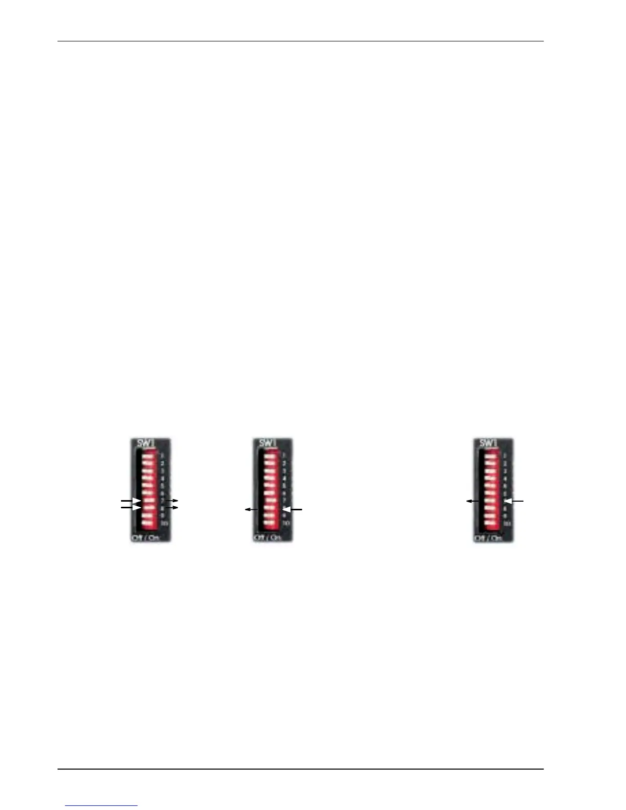
3.9.4 Switch 7 - Offset tuning
Switch 7 is used to start offset tuning on analog (command) input AIN0. The purpose of of fset
tuning is to remove DC offset voltages on analog input 0 (the command reference input) to
achieve a stationary motor shaft with 0VDC at the input. Confirm that the device supplying the
AIN0 command input is set to its intended zero output setting (nominally 0VDC) before starting
of fset tuning. When switch 7 is in the On position, offset tuning will start the next time Enable
(switch 8) is changed from On to Off.
On
7
Wait for 1 second
for offset tuning
to be completed.
Off
7
1. 2. 3. 4.
Off
8
On
8
Figure 19 - Offset tuning using switch 7 and 8
Leave switch 7 Of f in normal use. After of fset tuning, remember to set switch 8 to the On
position to allow the drive to be enabled. The switch positions are sampled every 100ms. The
Mint keyword ADCOFFSETTRIM canbeusedtoperformthesameaction.
3.9.5 Switch 8 - Enable
Switch 8 must be set to On to allow the drive to be enabled. The switch position is sampled
every 100ms. However, two other actions are necessary to enable the FlexDrive
II
:
H The enable input (see section 3.8) must be active.
H The drive must also be enabled by using a drive enable command (see section 3.8.3).