Basic Installation 3-5MN1902
H For effective cooling and maintenance, the FlexDrive
II
should be mounted on a smooth,
non- flammable vertical surface. The power handling capability is affected by the
temperature of the left side of the unit.
H At least 50mm (2 in) top and bottom clearance of the FlexDrive
II
must be provided for
airflow .
H If multiple FlexDrive
II
are being mounted side by side there must be 13mm (0.5 in)
between them. The FlexDrive
II
nearest the side of the cabinet / enclosure must be
separated from it by at least 13mm (0.5 in).
H To comply with CE directive 89/336/EEC an appropriate AC filter must be installed. The
external customer supplied 24VDC logic supply might also require a 24V filter. See section
3.4.7.
H The threaded holes in the top and bottom of the enclosure are for cable clamps. The holes
are threaded for M4 bolts no longer than 12mm (0.47 in) in length. Longer bolts may short
circuit the electrical components inside the FlexDrive
II
.
H Each D-type connector on the front panel of the FlexDrive
II
is secured using two
hexagonal jack screws (sometimes known as “screwlocks”). If a jack screw is removed
accidentally or lost it must be replaced with an identical jack screw with an external male
threaded section of 5mm (0.2 in). Jack screws with longer threads could damage or short
circuit internal components.
3.2.1 Mounting the FlexDrive
II
Ensure you have read and understood the Mechanical installation and location requirements in
section 3.2. Mount your FlexDrive
II
on its rear side, the side opposite to the front panel.
The FlexDrive
II
must be mounted upright to ensure adequate cooling (you can check this by
ensuring that the Hazardous Voltages warning information is clearly readable to you).
M5 bolts or screws should be used to mount the FlexDrive
II
.
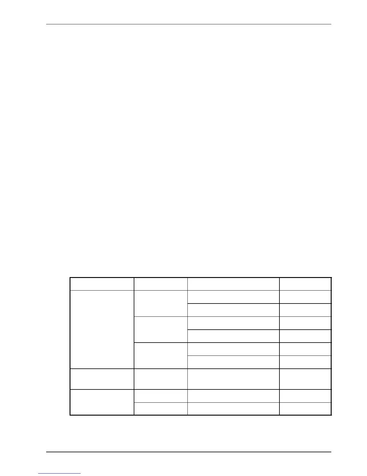
There are seven different package sizes depending on the specification of the FlexDrive
II
:
AC power
Current Factory fitted option Package size
Single-phase 2A without option A
with option B
5A without option C
with option D
7.5A without option D
with option D
230V
Three-phase
15A with or without option E
230- 460V
 Loading...

