Basic Installation 3-19MN1902
3.5.5 Motor brake connection
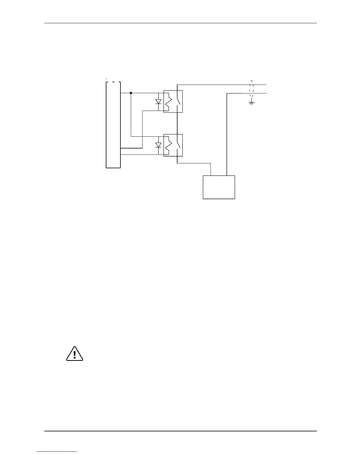
You might wish to wire a motor’s brake, via relays, to digital outputs on connector X3 (see
section 4.3.1). This provides a way for the Mint program to control the motor’s brake. A typical
circuit is shown in Figure 10.
C
D
from motor brake
connec tions
Separate
customer
supplied
24VDC supply
X3
8
18
19
DOUT0 (OUTX.0)
DOUT1 (OUTX.1)
CGND
Relay 2
Relay 1
+24VDC 0V
The i nner s hield
surrounding the
brake wires should
be earthed/grounded
at one point only.
The relay s have normally open
contac ts and are shown deactivated
(contacts open, brake engaged).
Figure 10 - Motor brake control circuit
This circuit uses the drive enable signal (configured using DRIVEENABLEOUTPUT to appear
on DOUT0) in conjunction with DOUT1. With this configuration, the following sequences can
be used to control the brake.
To engage the brake:
H The motor is brought to rest under normal control;
H Relay 2 is deactivated, causing the brake to engage;
H The drive is disabled. This removes power from the motor and causes Relay 1 to be
deactivated.
To disengage the brake:
H The drive is enabled, activating Relay 1;
H Power is applied to the motor to hold position under normal control;
H Relay 2 is activated, causing the brake to be disengaged.
CAUTION: The 24VDC power supply must be a separate supply as shown in Figure
10. Do not use the 24V supply powering the FlexDrive
II
digital outputs, or
the internally generated supply (if present). The brake wires often carry
noise that could cause erratic drive operation or damage. The brake
contacts must never be wired directly to the digital outputs. The relay(s)
should be fitted with a protective flyback diode, as shown.
The separate 24VDC supply used for the motor brake may also be used
to power the relay in the thermal switch circuit (section 3.5.4).

 Loading...
