Basic Installation 3-23MN1902
3.7.1.1 Resolver cable pin configuration
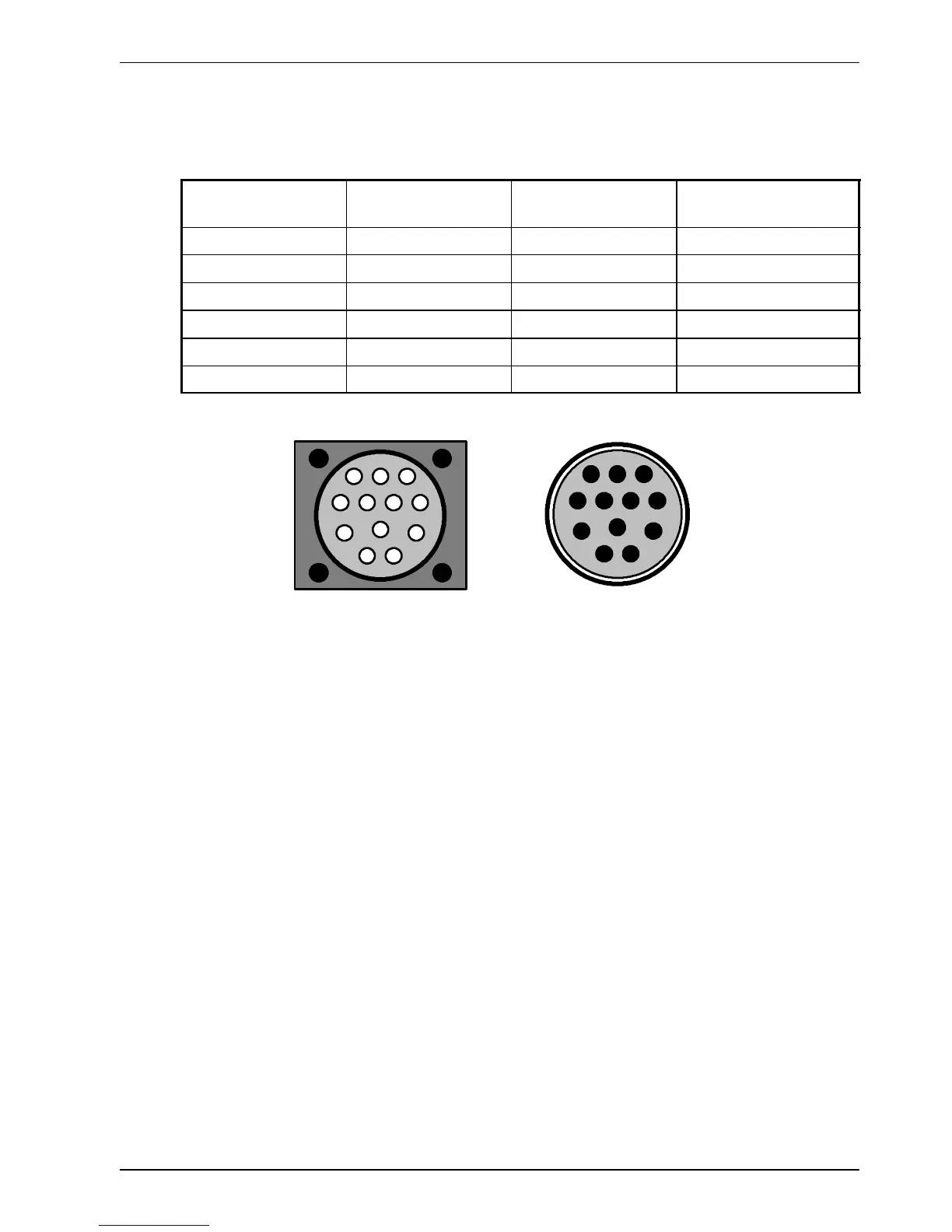
Figure 12 shows the pin configuration for a typical Baldor resolver feedback cable, part
number CBL030SF-ALCE.
Signal na me
FlexDrive
II
X8 pin
Motor / cable
pin
Baldor resolver cable
internal wire colors
REF+ 1 1 Red
REF- 6 2 Blue
COS+ 2 3 Green
COS- 7 4 Yellow
SIN+ 3 5 Pink
SIN- 8 6 Grey
1
2
3
45
6
7
89
10
11
12
Motor resol ver c onnector
(male)
Pins 7-12
are not used
and may not
be present
1
2
3
45
6
7
89
10
11
12
Cable connector end view
(female)
Figure 12 - Baldor motor resolve r c a ble pin configuration
The maximum recommended cable length is 30.5m (100ft).