Input / Output 4-13MN1902
CHA+
CHA--
CHB+
CHB--
+5V
DGND
1
6
2
7
3
8
9
5
X9
CHZ+
CHZ --
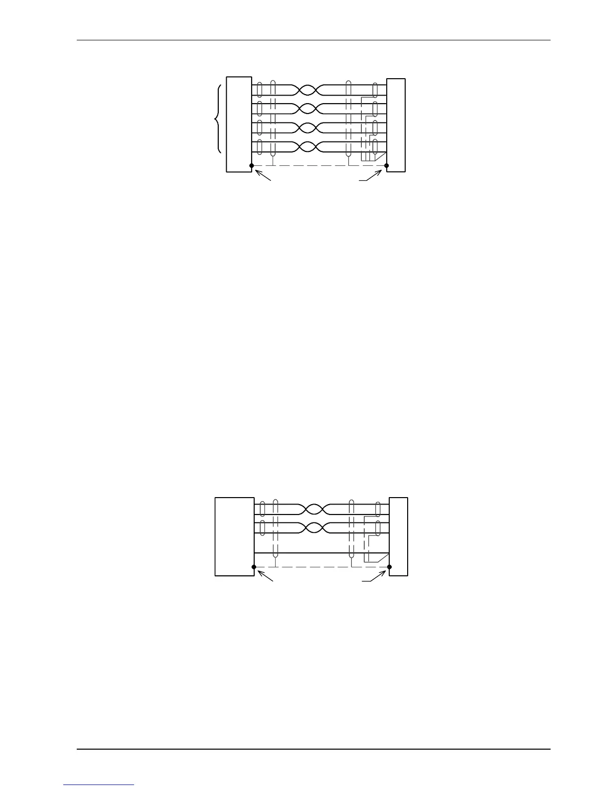
Twisted pai rs
Connect overall shield
to connector backshells.
Connect internal
shields to DGND.
Master
Encoder
Figure 31 - Differential encode r c onnections
4.4.2.1 Pulse and Direction following
The master encoder pulse and direction inputs accept 5V dif ferential line driver (RS422)
signals from an external source. The pulse frequency controls the speed, and the state of the
direction signal controls the direction of motion. A positive direction voltage (greater than
200mV) will result in motion in one direction. A negative direction voltage (less than -200mV)
will result in movement in the opposite direction.
The Mint keyword AUXENCODERMODE (bit 2) is used to configure X9 for pulse and direction
operation. If necessary, the sense of the direction input can be reversed in software using the
Mint keyword AUXENCODERMODE (bit 0). See the Mint help file for details.
Note: If X9 has been configured for pulse and direction input, the alternative pulse and
direction inputs, available on connector X3, cannot be used. See the Mint keyword
MASTERSOURCE.
Pulse +
Pulse - (GND)
Direction+
Direction - (GND)
DGND
1
6
2
7
5
X9
Twisted pai rs
Pulse and direction
source
Pulse
Direction
Connect overall shield
to connector backshells.
Connect internal
shields to DGND.
Figure 32 - Pulse and direction connections

 Loading...
