3-28 Basic Installation MN1902
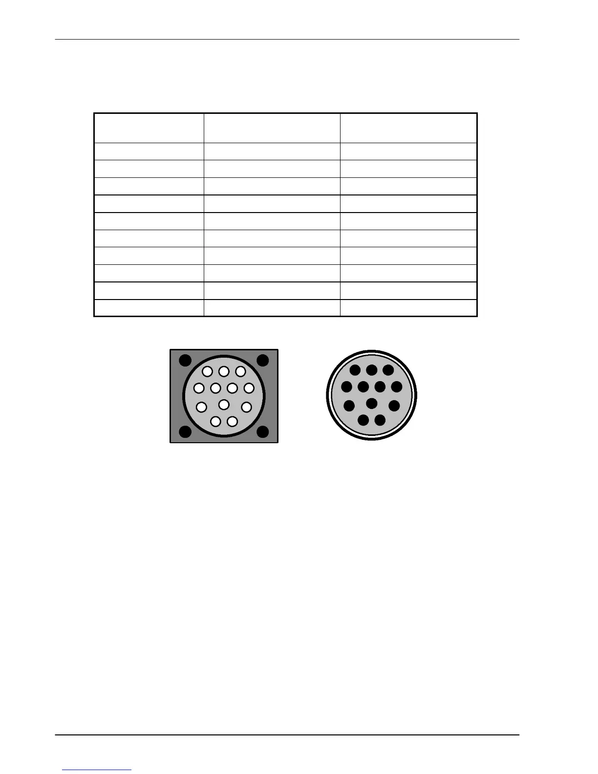
3.7.3.1 Absolute encoder cable pin configuration
Figure 17 shows the pin configuration for a typical Baldor absolute encoder feedback cable,
part number CBL030SF-KLCEA3.
Signal na me
FlexDrive
II
X8 pin
Motor / cable
pin
Data - 2 1
Sin A+ 13 2
Cos B+ 14 4
Clock- 9 5
Clock + 10 7
Cos B- 7 8
+5V 4 9
DGND 5 10
Sin A- 12 11
Data + 1 12
1
2
3
45
6
7
89
10
11
12
Motor abs olute encoder connector
(male)
1
2
3
45
6
7
89
10
11
12
Cable connector end view
(female)
Figure 17 - Baldor rot ary motor absolute e ncoder cable pin configuration
The maximum recommended cable length is 30.5m (100ft).

 Loading...
