9400200990 Rev I DGC-2020 Installation 6-17
Connections with LSM-2020 and CEM-2020
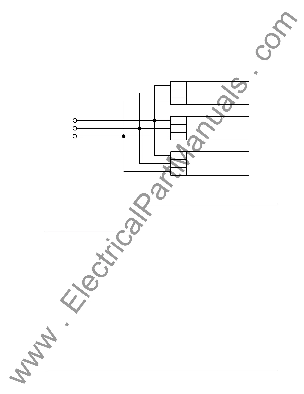
The LSM-2020 (Load Share Module) and CEM-2020 (Contact Expansion Module) are optional modules
that may be installed with the DGC-2020. These modules interface to the DGC-2020 via CANBus, thus
the CANBUS terminals are the only common connections (
Figure 6-11) between the DGC-2020, LSM-
2020, and
CEM-2020. Refer to Section 8, LSM-2020 (Load Share Module), for independent LSM-2020
connections. Refer to Section 9, CEM-2020 (Contact Expansion Module), for independent CEM-2020
connections. Refer to Connections, CAN Interface, in this section for details on DGC-2020 CANBus
connections.
10
11
12
LSM-2020
CANL
CANH
GND
P0053-21
1
5
4
CEM-2020
CANL
CANH
GND
50
49
48
DGC-2020
CANL
CANH
GND
CANH
CANL
GND/SHIELD
Figure 6-11. DGC-2020, LSM-2020, CEM-2020 CANBus Connections
INSTALLATION FOR CE SYSTEMS
For CE compliant systems, it may be required to route ac voltage and current sensing wires separately
from other wires.
INSTALLATION IN A SALT FOG ENVIRONMENT
If the DGC-2020 will be installed in a salt-fog environment, it is recommended that the backup battery for
the real-time clock be removed. Salt fog is known to be conductive and may short-circuit the battery.
Information on removing the backup battery for the real-time clock can be found in Section 7,
Maintenance and Troubleshooting.
www . ElectricalPartManuals . com