EasyManuals Logo

BIO RAD CFX96 User Manual

BIO RAD CFX96
158 pages
To Next Page IconTo Next Page
To Previous Page IconTo Previous Page
Page #13 background imageLoading...
Page #13 background image
System Installation
4
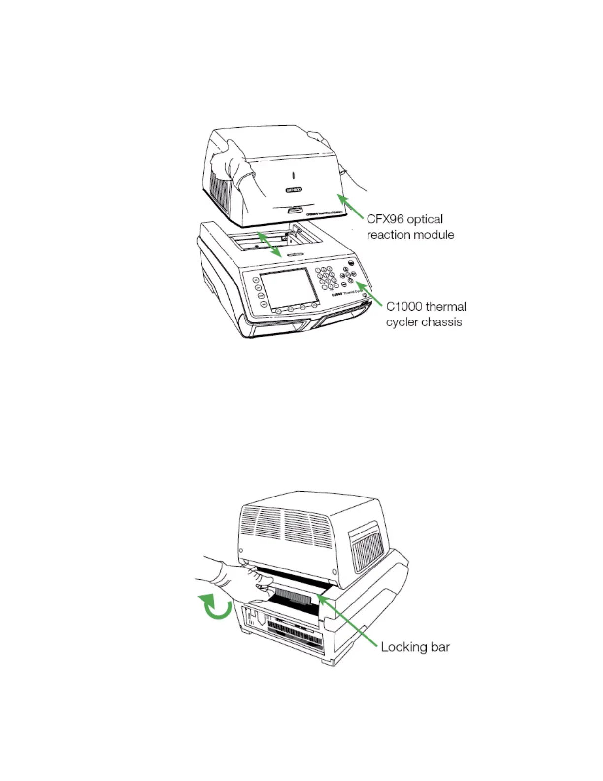
2. Lift the optical reaction module using the handle indents above the side air vents
(Figure 4).
Figure 4. Lifting the optical reaction module into the C1000 chassis.
3. Position the module in the reaction module bay of the C1000 chassis, leaving about 2 cm
of space in the front. When in the chassis bay, the optical module should be covering the
Bio-Rad logo in front of the bay of the C1000 chassis.
4. Reach around and pull up the locking bar of the C1000 until it is flush with the sides of
the module bay. This action moves the module forward, locking it into place (Figure 5)
Figure 5. Locking the optical module into place.

Table of Contents

Questions and Answers:

Question and Answer IconNeed help?

Do you have a question about the BIO RAD CFX96 and is the answer not in the manual?

BIO RAD CFX96 Specifications

General IconGeneral
Temperature Uniformity±0.4 °C
SoftwareCFX Maestro Software
Detection MethodReal-time PCR (qPCR)
Sample Capacity96-well plate
Excitation SourceLED
Ramp RateUp to 5°C/sec
Heating Rate5°C/sec
SensitivitySingle copy detection
Power Requirements100-240 V, 50/60 Hz
Temperature Range0–100 °C

Related product manuals