Operating Instructions ACTIVE06/07 147
06/07 Operating Instructions ACTIVE 147
14.4.9 Motor Potentiometer
The parameters
Reference Frequency Source 475, and Reference Percentage
Source
476 contain operation modes with motor potentiometer. Operation Mode 474
defines the behavior of the motor potentiometer function and the parameters
Fre-
quency Motorpoti Up
62, Frequency Motorpot. Down 63 or Percent Motorpoti
Up
72, Percent Motorpot. Down 73 the link to the available logic signals.
Motor Potentiometer Control
Motorpoti Up Motorpoti Down Function
0 0 Output signal does not change.
1 0 Output value rises at set ramp.
0 1 Output value drops at set ramp.
1 1 Output value is reset to initial value.
0 = contact open 1 = contact closed
14.5 Function Modules
14.5.1 Timer
The timer function can be linked to various functions for time-control of digital signals.
The parameters
Operation Mode Timer 1 790 and Operation Mode Timer 2 793
define the evaluation of the digital input signals and the unit of time of the time func-
tion.
Operation mode 790, 793 Function
0 - Off Signal output is switched off.
1 - Normal, Rising Edge, Sec.
Positive signal edge starts timer (trigger),
time 1 delays the output signal,
time 2 defines the signal period.
2 - Retrigger, Rising Edge, Sec.
Positive signal edge starts timer (trigger),
next positive signal edge within time 1 starts the
delay in time again (Retrigger), time 2 defines the
signal period.
3 -
AND-Connect., Rising Edge,
Sec.
Positive signal edge starts timer (trigger),
if no input signal is received within time 1 the
delay starts again (Retrigger),
if no input signal is received within time 2, the
signal period is terminated.
11 to 13
Operation modes 1...3, negative signal edge
starts timer.
101 to 113 Operation modes 1...3, [in minutes].
201 to 213 Operation modes 1...3, [in hours].
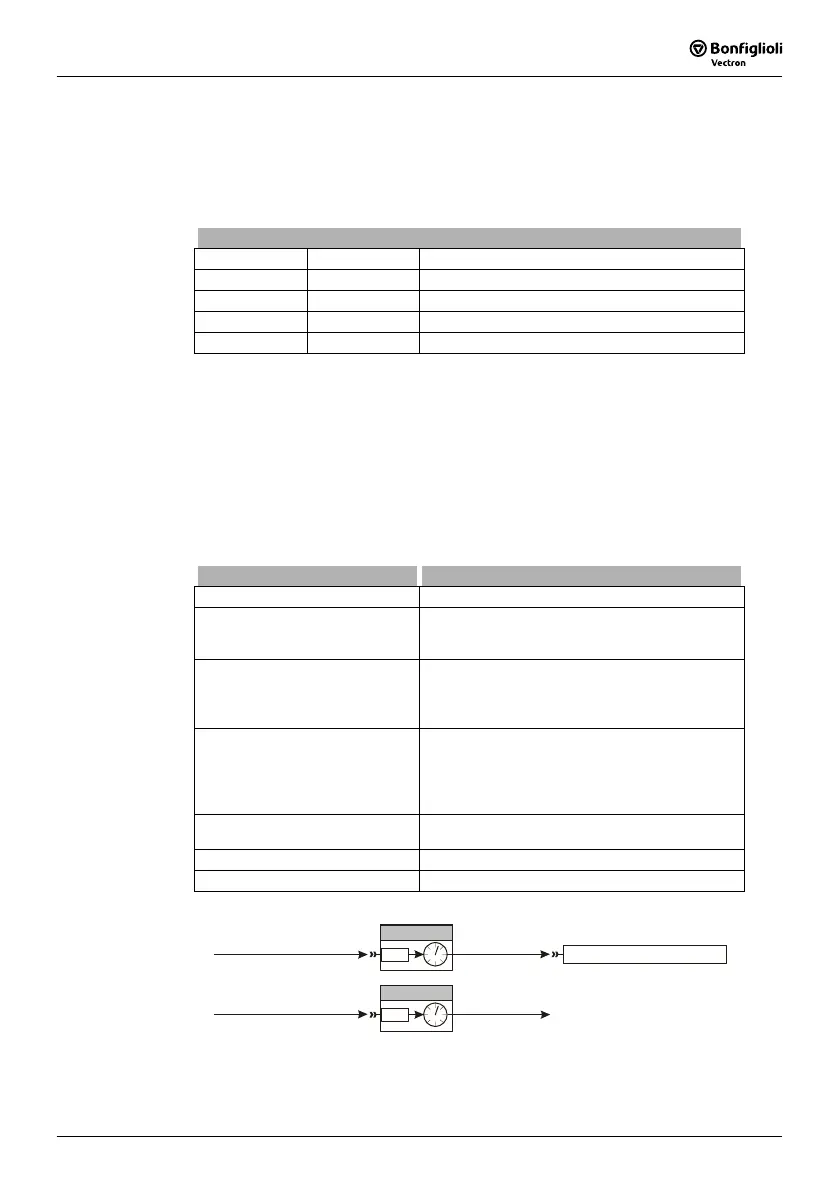
By default, the functions are linked according to the following illustration:
158 - Timer 1
Timer 1
83
P. 8 3
Data Set Change-Over 1
70
73 - S4IND
175 - Digital signal 1 159 - Timer 2
Timer 2
84
P. 8 4

 Loading...


