Operating Instructions ACTIVE 06/0726
26 Operating Instructions ACTIVE 06/07
4 Mechanical Installation
The frequency inverters of degree of protection IP20 are designed, as a standard, for
installation in electrical cabinets.
• During installation, both the installation and the safety instructions as well as the
device specifications must be complied with.
Warning! To avoid serious physical injuries or major material damage, only quali-
fied persons are allowed to work on the devices.
Warning! During assembly, make sure that no foreign particles (e.g. filings, dust,
wires, screws, tools) can get inside the frequency inverter. Otherwise
there is the risk of short circuits and fire.
The frequency inverters comply with protection class IP20 only if the
covers and terminals are mounted properly.
The units may only be used if these requirements are met.
4.1 ACT 201 (up to 3.0 kW) and ACT 401 (up to 4.0 KW)
The frequency inverter is mounted in a vertical position on the assembly panel by
means of the standard fittings.
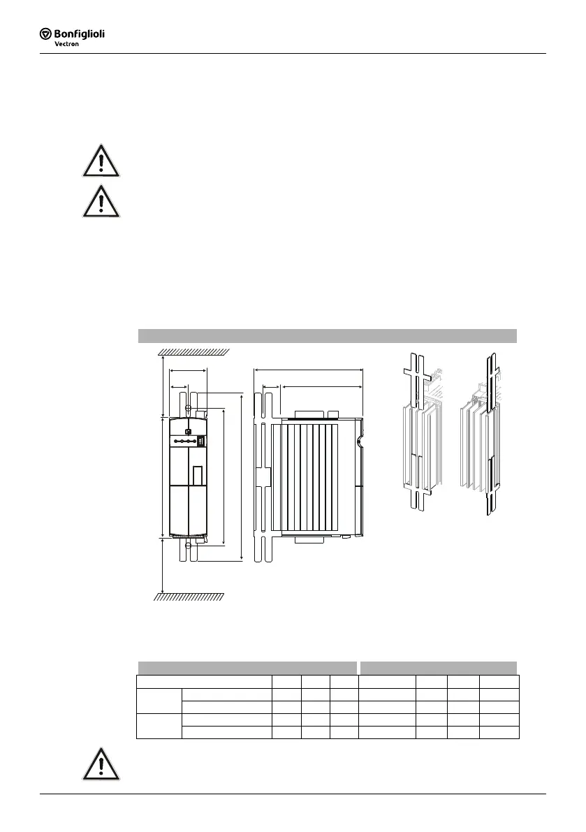
The following illustration shows the different mounting possibilities.
Standard installation
b
b1
a1
a a2
c
c1
x
x
x 100 mm
b1
Assembly is effected by inserting the long side of the fixing plate in the heat sink and
screwing it to the mounting plate.
The dimensions of the device and the installation dimensions are those of the stan-
dard device without optional components and are given in millimeters.
Dimensions in mm Installation dimensions in mm
Frequency inverter
a b c a1 a2 b1 c1
0.55 kW ... 1.1 kW
190 60 178 210 ... 230 260 30 133
ACT 201
1.5 kW ... 3.0 kW
250 60 178 270 ... 290 315 30 133
0.55 kW ... 1.5 kW
190 60 178 210 ... 230 260 30 133
ACT 401
1.85 kW ... 4.0 kW
250 60 178 270 ... 290 315 30 133
Caution! Mount the devices with sufficient clearance to other components so that
the cooling air can circulate freely. Avoid soiling by grease and air pollu-
tion by dust, aggressive gases, etc.

 Loading...


