Operating Instructions ACTIVE 06/0730
30 Operating Instructions ACTIVE 06/07
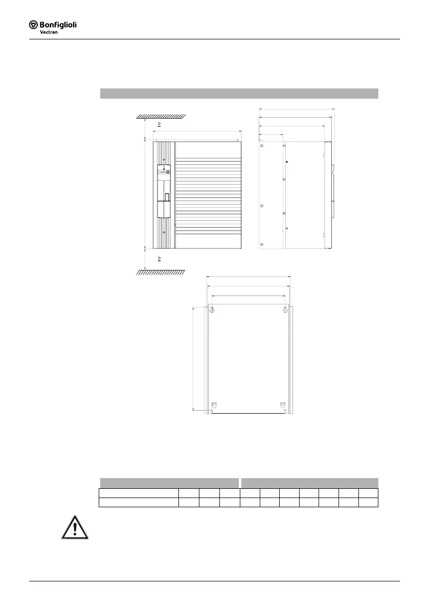
4.5 ACT 401 (75.0 up to 132.0 kW)
The frequency inverter is mounted in a vertical position on the assembly panel. The
following illustration shows the standard fitting.
Standard installation
a
b
c1
c2
c3
b1
b2
b3
a1
x
x
x
300 mm
x
300 mm
The diameter of the assembly holes is 9 mm.
Assembly is done by screwing the back plate of the frequency inverter to the assembly
panel.
The dimensions of the device and the installation dimensions are those of the stan-
dard device without optional components and are given in millimeters.
Dimensions in mm Installation dimensions in mm
Frequency inverter a b c a1 b1 b2 b3 c1 c2 c3
75.0 ... 132.0 kW 510 412 351 480 392 382 342 338 305 110
Caution! Mount the devices with sufficient clearance to other components so that
the cooling air can circulate freely. Avoid soiling by grease and air pollu-
tion by dust, aggressive gases, etc.

 Loading...


