Operating Instructions ACTIVE06/07 17
06/07 Operating Instructions ACTIVE 17
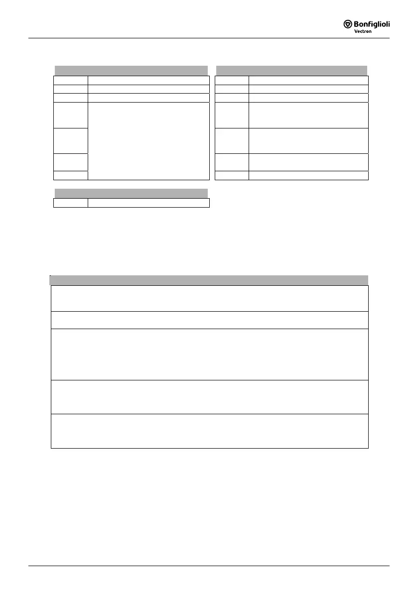
3.2 Technical data of control electronics
Control terminal X210A Control terminal X210B
X210A.1 DC 20 V output (I
max
=180 mA) X210B.1 Digital input
1)
X210A.2 Ground 20 V/ Ground 24 V (ext.) X210B.2 GND
X210A.3 Digital input Controller Release X210B.3 Digital output
1)
X210A.4 X210B.4 Multi-function output
1)
(voltage
signal proportional actual frequency
value, factory setting)
X210A.5 X210B.5 Supply voltage DC 10 V for refer-
ence value potentiometer,
(I
max
=4 mA)
X210A.6 X210B.6 Multi-function input
1)
(Reference
speed 0 … +10 V, factory setting)
X210A.7
Digital inputs
1)
X210B.7 Ground 10 V
Relay output X10
S3OUT.1 Monitoring function (factory setting)
1)
The control terminals are freely configurable.
Note:
The various configurations set the control terminals to defined adjustments. These adjustments can
be adapted to user-specific applications and various functions can be assigned to the freely pro-
grammable control terminals.
Technical data of the control terminals
Digital inputs (X210A.3…X210B.1): Low Signal: DC 0…3 V, High Signal: DC 12…30 V,
Input resistance: 2.3 kΩ, response time: 16 ms, PLC compatible
X210A.6 and X210A.7 additional: frequency signal: DC 0 V...30 V, 10 mA at DC 24 V, f
max
=150 kHz
Digital output (X210B.3): Low Signal: DC 0…3 V, High Signal: DC 12…30 V,
maximum output current: 40 mA, PLC compatible
Multi-function output (X210B.4):
analog signal: DC 24 V, maximum output current: 40 mA, pulse-width modulated (f
PWM
= 116 Hz),
digital signal: Low Signal: DC 0…3 V, High Signal: DC 12…30 V, output current: 40 mA, PLC compati-
ble,
frequency signal: output voltage: DC 0…24 V, maximum output current: 40 mA,
maximum output frequency: 150 kHz
Multi-function input (X210B.6):
analog signal: input voltage: DC 0… 10 V (R
i
=70 kΩ), input current: DC 0…20 mA (R
i
=500 Ω),
digital signal: Low Signal: DC 0…3 V, High Signal: DC 12 V…30 V, response time: 16 ms, PLC com-
patible
Conductor cross section:
The terminals are suitable for the conductor cross sections:
with wire end ferrule:
without wire end ferrule:
0.25…1.0 mm²
0.14…1.5 mm²

 Loading...


