Operating Instructions ACTIVE 06/07180
180 Operating Instructions ACTIVE 06/07
16.5.5.1 Limitation of field controller
The output signal of the field controller, the integrating and proportional components
are limited via parameter
Ref. Isd Upper Limit 743 and parameter Ref. Isd Lower
Limit
744. The guided commissioning has set the parameter Ref. Isd Upper Limit
743 according to the parameter
Rated Current 371.
Parameter Settings
No. Description Min. Max. Fact. sett.
743 Ref. Isd Upper Limit 0.1⋅I
FIN
o ⋅ I
FIN
I
FIN
744 Ref. Isd Lower Limit - I
FIN
I
FIN
0.0
The limits of the field controller define not only the maximum current occurring, but
also the dynamic properties of the controller. The upper and lower limits restrict the
modification speed of the machine flux and the torque resulting from it. In particular
the speed area above the nominal frequency should be observed for the modification
of the flux-forming component. The upper limit is to be estimated from the product of
the set magnetizing current and the correction factor
Reference Flux 717, although
the limit must not exceed the overload current of the drive.
16.5.6 Modulation Controller
The modulation controller, which is designed as an I regulator, automatically adapts
the output value of the frequency inverter to the machine behavior in the basic speed
area and in the field weakening area. If the modulation exceeds the value set with
parameter
Reference Modulation 750, the field-forming current component and thus
the flux in the machine are reduced.
In order to make the best possible use of the voltage available, the figure selected via
parameter
Operation mode 753 is put into proportion to the DC link voltage. That
means that with a high mains voltage there is also a high output voltage available, the
drive only reaches the field weakening area later and produces a higher torque.
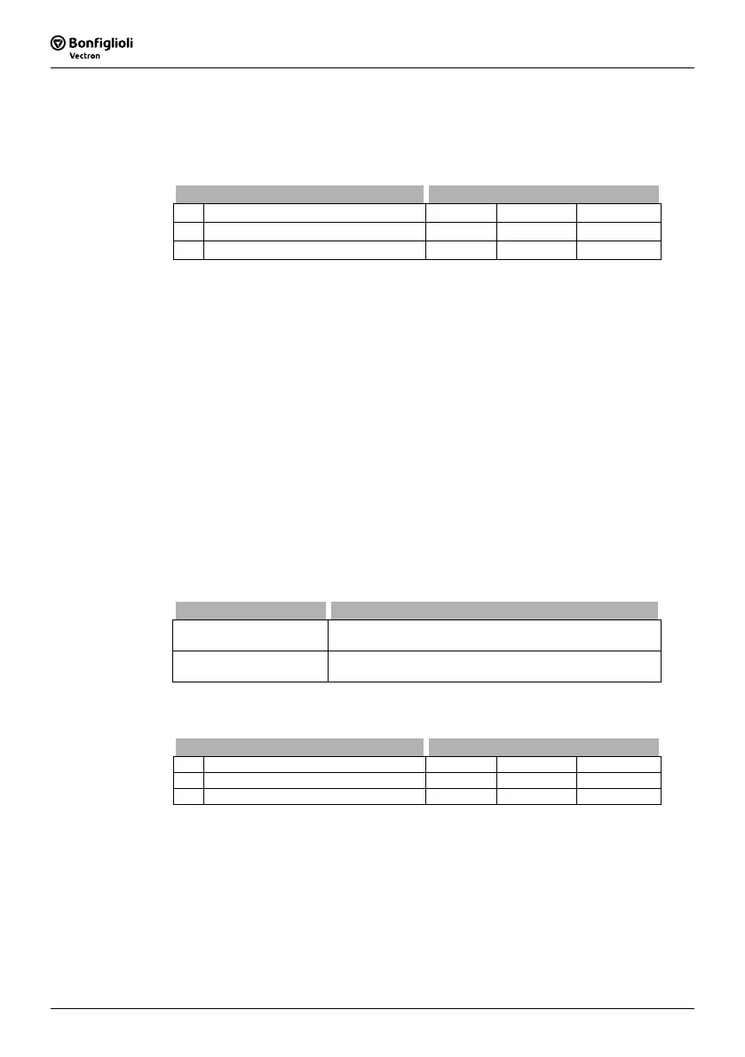
Operation mode 753 Function
0 - Usq-Control
The modulation is calculated from the ratio of torque-
forming voltage component U
sq
to the DC link voltage.
1 -
V-Absolute Value
Control
The modulation is calculated from the absolute voltage
value to the DC link voltage ratio.
The integrating part of the modulation controller is to be set via parameter
Integral
Time
752.
Parameter Settings
No. Description Min. Max. Fact. sett.
750 Reference Modulation 3.00 % 105.00 % 102.00 %
752 Integral Time 0.0 ms 1000.0 ms 10.0 ms

 Loading...


