Operating Instructions ACTIVE06/07 127
06/07 Operating Instructions ACTIVE 127
13.11 Repetition frequency input
The use of a frequency signal completes the various possibilities of the reference
value specification. The signal at one of the available digital inputs is evaluated ac-
cording to the selected
Operation Mode 496.
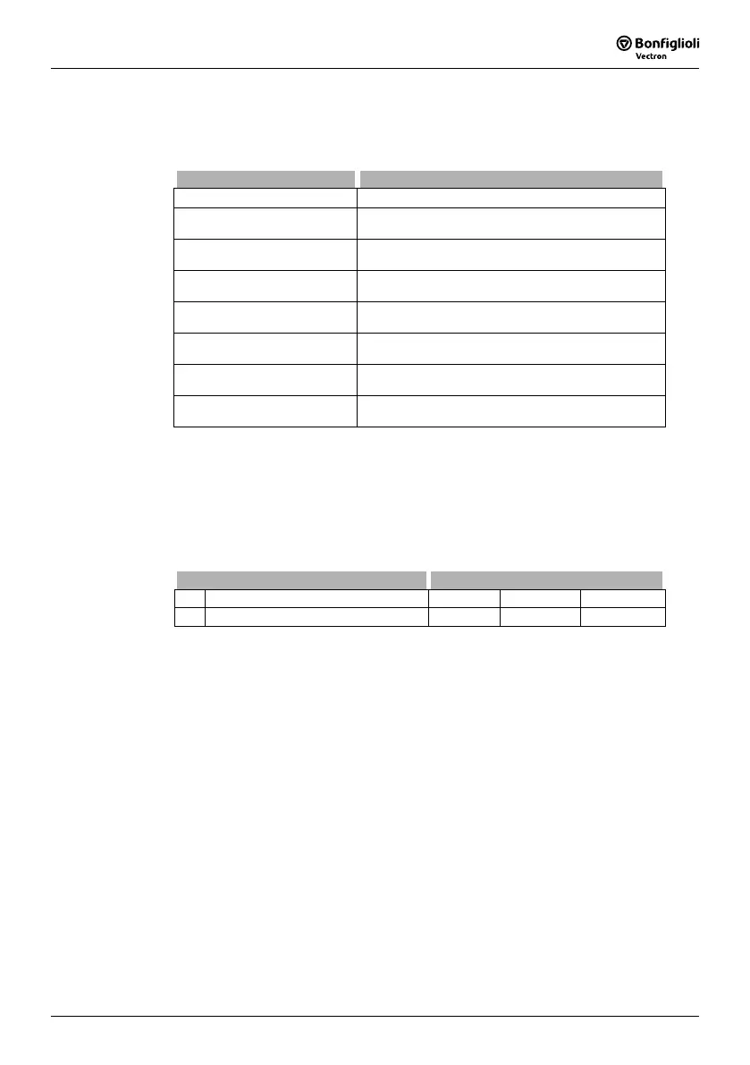
Operation Mode 496 Function
0 - Off Repetition frequency is zero.
21 -
S2IND
Single Evaluation pos.
One edge of the frequency signal at terminal
X210A.4 is evaluated with a positive sign.
22 -
S2IND
Double Evaluation pos.
Both edges of the frequency signal at terminal
X210A.4 are evaluated with a positive sign.
31 -
S3IND
Single Evaluation pos.
One edge of the frequency signal at terminal
X210A.5 is evaluated with a positive sign.
32 -
S3IND
Double Evaluation pos.
Both edges of the frequency signal at terminal
X210A.5 are evaluated with a positive sign.
61 -
S6IND
Single Evaluation pos.
One edge of the frequency signal at terminal
X210B.1 is evaluated with a positive sign.
62 -
S6IND
Double Evaluation pos.
Both edges of the frequency signal at terminal
X210B.1 are evaluated with a positive sign.
121 to 162
Operation modes 21 to 62 with evaluation of the
frequency signal, but with a negative sign.
Note: If a digital input is configured as a repetition frequency input, this input
cannot be used for other functions.
Check the link of the digital inputs to other functions.
The signal frequency at the selected repetition frequency input can be scaled via the
parameter
Divider 497. The parameter figure is comparable with the division marks
of a speed sensor per rotation of the drive. The frequency limit of the parameterized
digital input is to be taken into account for the frequency of the input signal.
Parameter Settings
No. Description Min. Max. Fact. sett.
497 Divider 1 8192 1024
Note: The reference value specification within the different functions enables
the use of the repetition frequency signal as a percentage figure. A sig-
nal frequency of 100 Hz at the repetition frequency input corresponds to
100%, 1 Hz corresponds to 1%. The parameter
Divider 497 is to be
used in a way comparable with the speed sensor simulation.

 Loading...


