Operating Instructions ACTIVE 06/0732
32 Operating Instructions ACTIVE 06/07
5.1 EMC Information
The frequency inverters are designed according to the requirements and limit values
of product norm EN 61800-3 with an interference immunity factor (EMI) for operation
in industrial applications. Electromagnetic interference is to be avoided by expert in-
stallation and observation of the specific product information.
Measures
− Install the frequency inverters and commutating chokes on a metal mounting
panel. Ideally, the mounting panel should be galvanized.
− Provide proper equipotential bonding within the system or the plant. Plant compo-
nents such as control cabinets, control panels, machine frames, etc. must be con-
nected by means of PE cables.
− Connect the frequency inverter, the commutating choke, external filters and other
components to an earthing point via short cables.
− Keep the cables as short as possible, make sure that cables are installed properly
using appropriate cable clamps, etc.
− Contactors, relays and solenoids in the electrical cabinet are to be provided with
suitable interference suppression components.
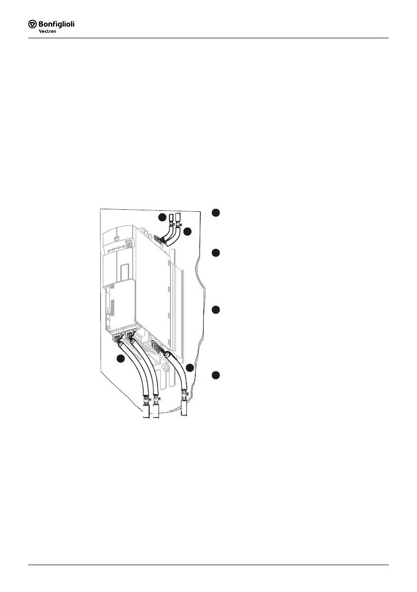
A
Mains Connection
The length of the mains supply cable is not lim-
ited. However, it must be installed separate from
the control, data and motor cables.
B
DC link connection
The frequency inverters are to be connected to
the same mains potential or a common direct
voltage source. Cables longer than 300 mm are to
be shielded. The shield must be connected to the
mounting panel on both sides.
C
Control Connection
The control and signal cables must be kept physi-
cally separate from the power cables. The shield
of the control cables is to be connected to ground
potential properly, i.e. with good conductivity, on
both sides. Analog signal lines are to be con-
nected to the shield potential on one side.
D
Motor and brake resistor
A
B
C
D
The shield of the motor cable is to be connected
to ground potential properly on both sides. On the
motor side use a metal compression gland. On the
frequency inverter side an appropriate shield
clamp is to be used. The signal cable used for
monitoring the motor temperature must be kept
separate from the motor cable. Connect the shield
of this line on both sides. If a brake resistor is
used, the connection cable must also be shielded,
and the shield is to be connected to earth poten-
tial on both sides.
Attention! The frequency inverters meet the requirements of the low-voltage direc-
tive 73/23/EEC and the requirements of the EMC directive 89/336/EEC.
The EMC product standard EN 61800-3 relates to the drive system. The
documentation provides information on how the applicable standards
can be complied if the frequency inverter is a component of the drive
system. The declaration of conformity is to be issued by the supplier of
the drive system.

 Loading...


