Operating Instructions ACTIVE 06/07192
192 Operating Instructions ACTIVE 06/07
18 Actual Values
The various control functions and methods include electrical control variables and
various calculated actual values of the machine or system. The different actual values
can be read out for operational and error diagnosis via a communication interface or
in the VAL menu branch of the operating unit.
18.1 Actual Values of the Frequency Inverter
The modular hardware of the frequency inverter enables application-specific adapta-
tion. Further actual value parameters can be displayed as a function of the selected
configuration and the installed expansion cards.
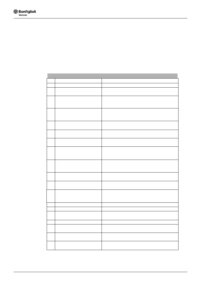
Actual Values of the Frequency Inverter
No. Description Function
222 DC link voltage Direct voltage in the DC link.
223 Modulation
Output voltage of the frequency inverter relative
to the mains voltage (100% = U
FIN
).
228
Internal Reference Fre-
quency
Sum of the Reference Frequency Sources 475 as
a reference value from the frequency reference
value channel.
229 Reference Percentage Value
Sum of the
Reference Percentage Sources 476
as a reference value from the reference percent-
age channel.
230 Actual Percentage Value
Actual value signal on the
Actual Percentage
Source
478.
244 Working Hours Counter
Operating hours in which the output stage of the
inverter is active.
245 Operation Hours Counter
Operating hours of the frequency inverter in
which supply voltage is available.
249 Active data set
The data set actively in use according to
Data
Set Change-Over 1
70 and Data Set Change-
Over 2
71.
250 Digital Inputs
Decimally coded status of the six digital inputs
and of multifunctional input 1 in
Operation Mode
452 - digital input.
251 Analog Input MFI1A
Input signal on multifunctional input 1 in
Opera-
tion Mode
452 - analog input.
252 Repetition frequency input
Signal on repetition frequency input according to
Operation Mode 496.
254 Digital Outputs
Decimally coded status of the two digital outputs
and of multifunctional output 1 in
Operation
Mode
550 – digital.
255 Heat Sink Temperature Measured heat sink temperature.
256 Inside Temperature Measured inside temperature.
257 Analog Output MFO1A
Output signal on multifunctional output 1 in
Op-
eration Mode
550 – analog.
259 Current Error Error message with error code and abbreviation.
269 Warnings
Warning message with error code and abbrevia-
tion.
275 Controller Status
The reference value signal is limited by the con-
troller coded in the controller status.
278
Repetition frequency output
MFO1F
Output signal on multifunctional input 1 in
Op-
eration Mode
550 – repetition frequency.
Note: The actual values can be read out and monitored in the VAL menu
branch of the operating unit. The parameter
Control Level 28 in the
PARA menu branch defines the selection of the actual value parameters.

 Loading...


