Operating Instructions ACTIVE 06/0728
28 Operating Instructions ACTIVE 06/07
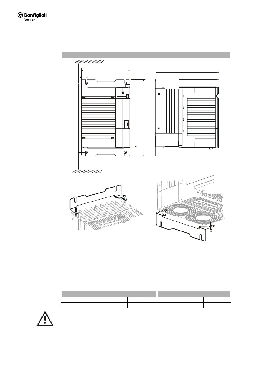
4.3 ACT 401 (18.5 up to 30.0 kW)
The frequency inverter is mounted in a vertical position on the assembly panel by
means of the standard fittings. The following illustration shows the standard fitting.
Standard installation
c
c1
x 100 mm
x
a
a1
a2
b
b1
x
fixing bracket top
(fixing with screws )
M4x20
fixing bracket bottom
(fixing with screws )
M4x70
Assembly is done by screwing the two fixing brackets to the heat sink of the fre-
quency inverter and the assembly panel.
The frequency inverters are provided with fixing brackets, which are fitted using four
thread-cutting screws. The dimensions of the device and the installation dimensions
are those of the standard device without optional components and are given in milli-
meters.
Dimensions in mm Installation dimensions in mm
Frequency inverter
a b c a1 a2 b1 c1
18.5 kW ... 30.0 kW
250 200 260 270 … 290 315 20 160
Caution! Mount the devices with sufficient clearance to other components so that
the cooling air can circulate freely. Avoid soiling by grease and air pollu-
tion by dust, aggressive gases, etc.

 Loading...


