Operating Instructions ACTIVE 06/07186
186 Operating Instructions ACTIVE 06/07
17.4.1 Dimensioning of Brake Resistor
The following values must be known for dimensioning:
− Peak braking power P
b Peak
in W
− Resistance Rb in Ω
− Duty cycle DC in %
• Calculation of peak braking power P
b Peak
P
b Peak
= Peak braking power in W
J = Moment of inertia of drive system kgm
2
n
1
= Speed of drive system before the braking op-
eration in min
-1
n
2
= Speed of drive system after the braking opera-
tion in min
-1
b
2
2
2
1
Peak b
t182
nnJ
P
⋅
−⋅
=
t
b
= Braking time in s
• Calculation of resistance R
b
R
b
=
Resistance in
Ω
U
d BC
= Switch-on threshold in V
Peak b
2
BC d
b
P
U
R =
P
b Peak
= Peak braking power in W
The switch-on threshold U
d BC
is the DC link voltage at which the brake resistor is
switched on. The switch-on threshold can be set, as described above, via parameter
Trigger Threshold 506.
Caution! The resistance of the brake resistor must not be less than the minimum
value R
b min
-10%. The values for R
b min
are listed in chapter "Technical
Data".
If the calculated resistance R
b
of the brake resistor is between two standard series
values, the lower resistance is to be selected.
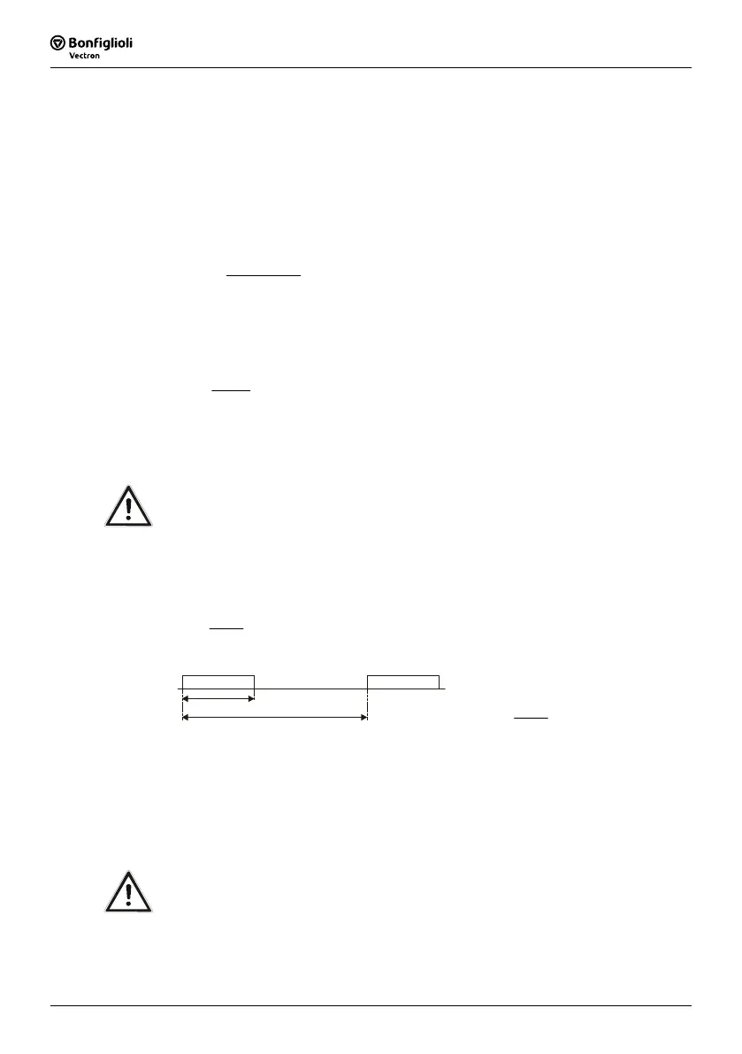
• Calculation of duty cycle DC
DC = Duty cycle
t
b
= Braking time
cycle
t
b
t
CD =
t
cycle
= Cycle time
Example:
t
b
= 48 s, t
cycle
= 120 s
t
cycle
t
b
%404.0
cycle
t
b
t
CD ===
In the case of infrequent short braking operations, typical values of the duty cycle DC
are at 10 %, for long braking operations (
≥ 120 s) typical values are at 100%. In the
case of frequent deceleration and acceleration operations, it is recommended that the
duty cycle DC be calculated according to the above formula.
The calculated values for P
b Peak
, R
b
and DC can be used by the resistor manufacturers
for determining the resistor-specific permanent power.
Warning! The brake resistor is to be connected according to the specifications and
instructions in chapter "Connection of a Brake Resistor".

 Loading...


