Operating Instructions ACTIVE 06/07138
138 Operating Instructions ACTIVE 06/07
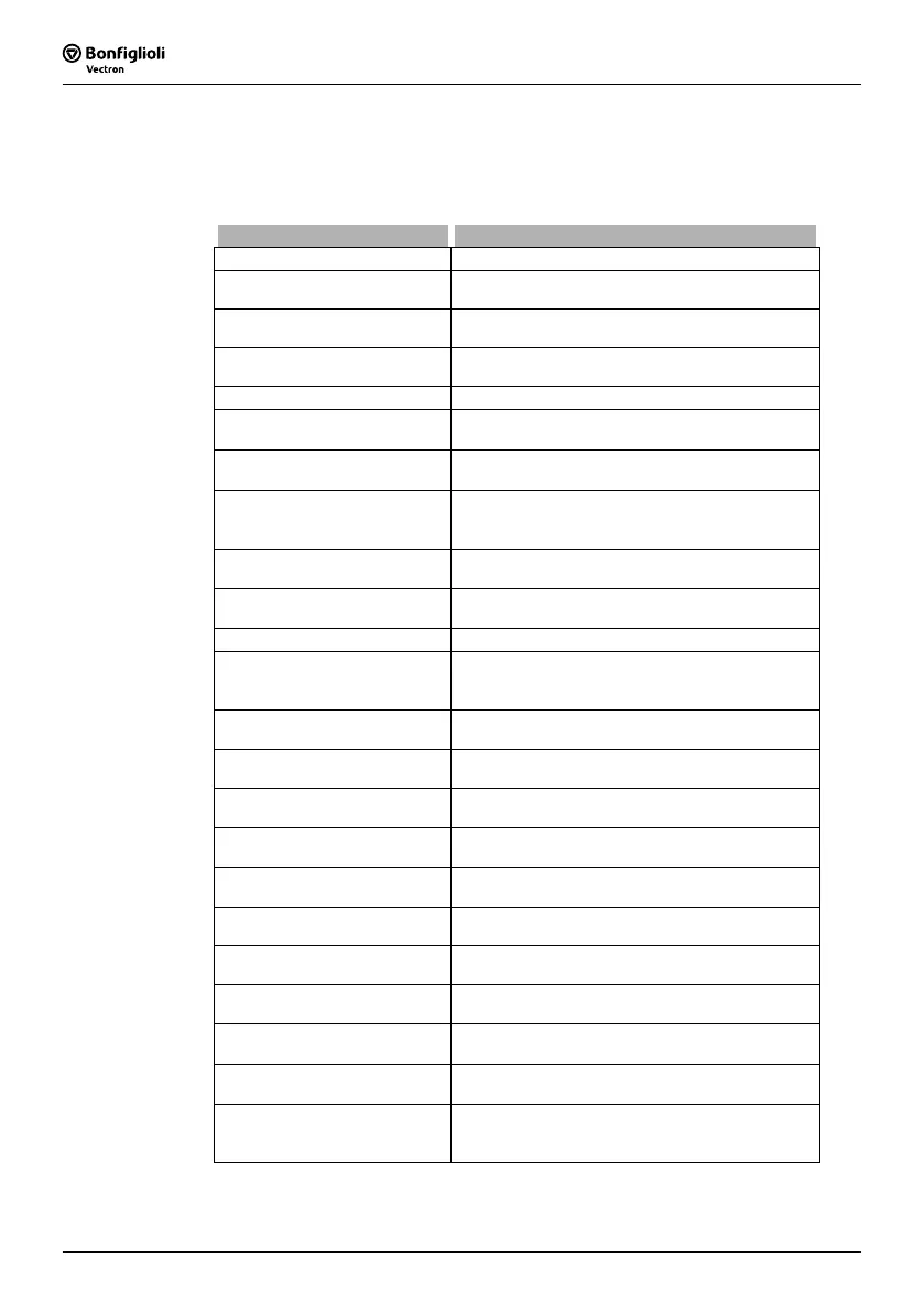
14.3.7 Warning Mask
The logic signals of various monitoring and control functions can be set via the opera-
tion mode for parameter
Create Warning Mask 536. According to the application, any
number of warnings and controller status messages can be combined. This enables
internal or external control via a common output signal.
Create Warning Mask 536 Function
0 - No Change Configured warning mask is not modified.
1 - Activate everything
The warnings and controller status messages stated
are linked in the warning mask.
2 - Activate all Warnings
The warnings reports stated are linked in the warn-
ing mask.
3 -
Activate all Controller
States
The controller status reports stated are linked in the
warning mask.
10 - Warning Ixt The frequency inverter is overloaded.
11 - Warning Short-Term Ixt
Overload reserve for 1 s minus the
Warning Limit
Short-Term Ixt
405 has been reached.
12 - Warning Long-Term Ixt
Overload reserve for 60 s minus the
Warning Limit
Long-Term Ixt
406 has been reached.
13 -
Warning Heat Sink Tem-
perature
Max. heat sink temperature T
K
of 80 °C minus the
Warning Limit Heat Sink Temperature 407 has
been reached.
14 -
Warning
Inside Temperature
Max. inside temperature T
i
of 65 °C minus the
Warning Limit Inside Temperature 408 reached.
15 - Warning Limit
The controller stated in
Controller Status 355 limits
the reference value.
16 - Warning Init Frequency inverter is initialized.
17 -
Warning Motor Tempera-
ture
Warning behavior according to parameterized
Mo-
tor Temp. Operation Mode
570 at max. motor
temperature T
PTC
.
18 -
Warning
Phase Failure
Phase Supervision 576 reports a phase failure.
19 -
Warning
Motor Protection Switch
Operation Mode 571 for the motor protective
switch has triggered.
20 - Warning Fmax
The
Maximum Frequency 419 has been exceeded.
The frequency limitation is active.
21 -
Warning
Analog Input MFI1A
The input signal is lower than 1V/2mA according to
the operation mode
Error/Warning Behavior 453.
22 -
Warning
Analog Input EM-S1INA
The input signal is lower than 1V/2mA according to
the operation mode
Error/Warning Behavior 453.
23 -
Warning
System bus
A Slave at the system bus signals a fault;
Warning is only relevant with option EM-SYS.
24 - Warning Udc
The DC link voltage has reached the type-
dependent minimum value.
25 - Warning V-belt
The
Operation Mode 581 for V-belt monitoring
signals no-load operation of the application.
30 -
Controller
Udc Dynamic Operation
Controller is active according to the
Operation
Mode
670 for the voltage controller.
31 - Controller Shutdown
The output frequency in the case of a mains failure
is below the
Shutdown Threshold 675.
32 - Controller Mains Failure
Failure of the mains voltage and power regulation
active according to
Operation Mode 670 for the
voltage controller.

 Loading...


