Operating Instructions ACTIVE06/07 159
06/07 Operating Instructions ACTIVE 159
16.2 Voltage controller
The voltage controller contains the functions necessary for monitoring the DC link
voltage.
− The DC link voltage which rises in generator operation or in the braking process of
the 3-phase machine is controlled to the set limit value by the voltage controller.
− The mains failure regulation uses the rotation energy of the drive to bridge short-
term power failures.
The voltage controller is set with the parameter
Operation Mode 670 in accordance
with the application.
Operation mode Function
0 - Off The function is switched off.
1 - Udc-Limitation active
Overvoltage controller switched on,
with motor chopper.
2 - Mains Support active
Mains failure regulation switched on,
with motor chopper, for quick shutdown.
3 -
Udc-Limit. & Mains
Supp. active
Overvoltage controller and mains failure regulation
switched on, with motor chopper.
12 -
Mains Support active,
Chopper not active
Mains failure regulation switched on,
without motor chopper.
13 -
Udc-Limit. & Mains
Supp. active,
without Chopper
Overvoltage controller and mains failure regulation
switched on, without motor chopper.
The function motor chopper is available in the field-oriented control methods (in con-
figurations 210, 230, 410, 411 and 430).
When an operation mode with motor chopper is selected, set the Trigger Threshold
507 to the Reference DC-Link Limitation 680.
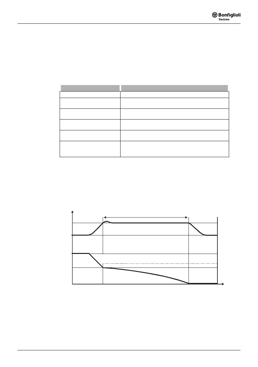
Operation mode Overvoltage control,
Voltage controller: Parameter
Operation Mode 670 = 1
Ud
Ud, f
681
f
t
421 or 423
680
Overvoltage controller active
The overvoltage controller prevents a switch-off of the frequency inverter in generator
operation. The reduction of the drive speed by a ramp gradient selected via the pa-
rameter
Deceleration Clockwise 421 or Deceleration Anticlockwise 423 can lead to
an overvoltage in the DC link.

 Loading...


